In our previous articles we have learned comprehensively regarding the ICs LM2907/LM2917 which are fundamentally frequency to voltage converter ICs, and are ideally applicable in all such relevant fields. Here we see how the same chip can be applied for making a vehicle speed limit alarm circuit.
Using a Single IC for Speed Detection

As per the explained example the IC could be used for making a simple speed limit switch circuit which in turn could be applied in vehicles for detecting over-speeds and consecutively alarming or preventing the vehicle from crossing the set dangerous mark.
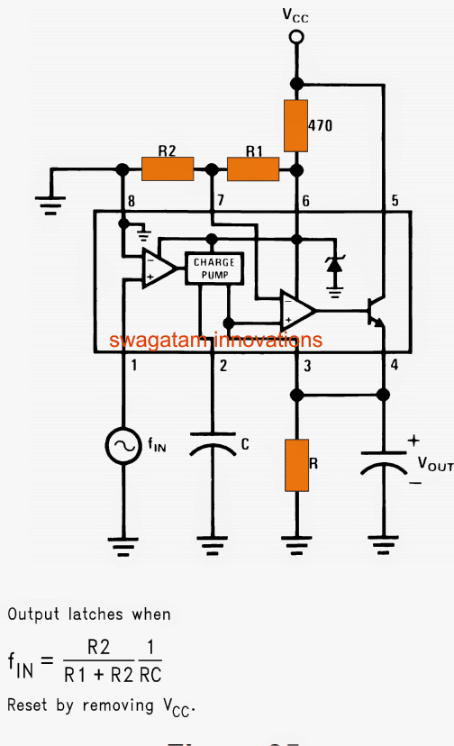
As shown in the below diagram a single LM2917 is enough for designing the proposed speed limiter circuit along with a few external passive parts.
Referring to the diagram, the input pin#1 receives the signal from the wheels of the vehicle through a magnet and pickup coil arrangement or through a Hall effect sensor circuit.
Circuit Operation
You may refer to this article for knowing the basic set up of the wheel and pickup coil in the given diagram.
The function is pretty much identical to the previously explained speedometer circuit functioning:
The applied speed info in the form of pulses corresponding to the rotating wheel count is sensed by the differential opamp whose inverting input is referenced to ground for maximum sensitivity.
The output from this opamp is fed to the next sage which is the charge pump stage responsible for tracking/holding/boosting the info in the form of a steady DC.
This function relies particularly on the value of C a pin#2 of the IC.
The above info is yet again amplified and compared by the subsequent opamp and common collector transistor stage.
The output is terminated at pin#4 of the IC via the emitter of the internal common collector transistor.
Formula for Setting the Speed Limit
As per the formula, the speed limit alarm can be set and calculated by using the formula:
f(in) = R2/R1+R2 x 1/RC
Once the set limit is reached, the IC detects it and produces a high logic at pin#4 which is equal to the supply voltage of the circuit.
This high logic may be used for sounding an alarm, deactivating the engine or for triggering other similar preventive measures.
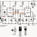
Circuit Diagram
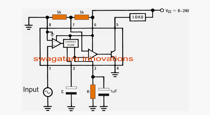
A typical implementation of the above circuit can be witnessed in the following diagram.
Here the load or the speed alarm unit is connected at the transistor collector pin#5 output instead of pin#4 as narrated in the above section.
The collector load configuration provides the advantage of better current gain allowing a higher wattage device such as a relay or an alarm to be directly used with the circuit.
Application Circuit

Questions & Answers
Hello! I need a circuit for indicating a running engine of a car. The goal is to use a relay to disable the starter when the engine is running. My idea is to use an inductive sensor and with a trimmer to set at what rpm, respectively pulses, the relay will turn on, disabling the starter. Thank you!
Hi, I think the last circuit design from the following article should be able to fulfil your requirement:
https://www.homemade-circuits.com/make-this-car-over-speed-limit-warning/
hi we work on project on vehicle speed alarm ..when vehicle move above 40 ..siren will be on ..in particular area after put one switch then after circuit not work ..so suggest above and what is cost of this single project .
Hi, you can implement the concept explained above. Replace the load with any DC buzzer, and calculate the RC elements with the help of the formula to fix them at a frequency proportionate to 40 km/H
Sir, i am making a project regarding the same topic. Would you please explain what is the difference between this circuit and another Car Speed Limit Warning Indicator Circuit
you made using IC 555.
i am referring to this : https://www.homemade-circuits.com/make-this-car-over-speed-limit-warning/
Manu, both the designs will do the job the for you appropriately, however the IC 555 being easily available appears to be a friendlier option
Dear Sir,
Is this circuit will also run for Bus or not.
Because I’m going to Indicate Over speed of bus.
Can you suggest me Please……..
Hi Darshan, the circuit can be installed with any vehicle, however the wheel of the vehicle will need to be configured with a magnet, and an aligned hall effect sensor hooked up with the circuit input. Once this is done, the speed detection and cut off can be easily implemented
Vehicle Speed Limit Alarm Circuit
Hi
Can you confirm the following RC for 71Hz R=180Kohms and C=39nF. Can you also tell me what type of capacitor the 39nF and the 10microF need to be.
Many thanks Paul
Hi, sorry it will difficult for me to confirm the result due to lack of time….the capacitor can be any metallized polyester type for better reliability.
Thank you for this information. I am using a reed switch for my input so have pulsing dc as an input. Can I use this circuit or do I need to look for a different input circuit to suit this chip.
Many thanks Paul
Hi, thanks,
What exactly do you want to check? is it the frequency of the pulse?
If the frequency is too low then may be the above circuit wouldn't work correctly.
Sir….I wan to make a circuit with a speed limit detector that senses anything that is speeding and convert that enerygy to electrical energy and straightly to a buzer. Need your reply quickly.
I think you are referring to a speed gun circuit, sorry at the moment I do not have this circuit
Sir, plz tell me the circuit which can be activated once the button is pressed but de-activation must me done by other switch
gurpreet, please refer to the set/reset latch circuit under this post:
https://www.homemade-circuits.com/2011/12/how-to-build-simple-transistor-circuits.html
Sir, please Suggest me The switching circuit as mention above. Thanks for your fast response
gurpreet, please refer to the set/reset latch circuit under this post:
https://www.homemade-circuits.com/2011/12/how-to-build-simple-transistor-circuits.html
Dear Sir,
I want to make a laser security system, Which circuit must be used to activate the alarm, the switching circuit must be like once the laser beam is displaced from the photo cell the alarm must be activated until i want to stop it. And it must be more helpful if i can receive a signal in cellphone or any radio device instead of using a buzzer.Sir the system must be a long life circuit not an ordinary one. Sir can i use ir laser if can can you link me an online purchasing link. Thanks…
Dear Gurpreet,
Getting a cell phone alarm could be very costly, you will have to install a GSM module for that which could cost around Rs.2000/- to Rs.3000/- however a short distance FM wireless transmission could be possible cheaply…
I'll try to figure it out and possibly post it soon.