A trustworthy and adaptable power source is essential in the world of electronic circuits. The design we present here not only offers a regulated output voltage range of 50V to 100V but also integrates safeguards to prevent potential mishaps. Let's examine the specifics of this power supply circuit, discovering its special characteristics and how it functions.
Circuit Diagram
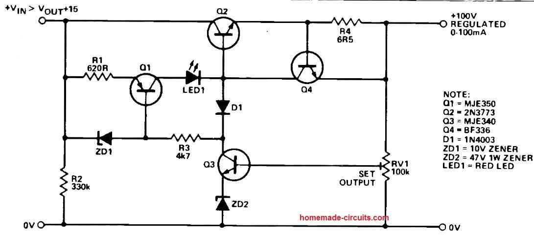
Output Voltage Range and Current Limitation
The essence of this power supply design is its capacity to generate an output voltage ranging from 50V to 100V.
However, what makes it truly remarkable is its built-in current limitation feature.
The output current is effectively capped at 100mA, ensuring a controlled power delivery to the connected load.
To cater to higher current demands, simple modifications can be made.
Short Circuit and Low Load Resistance Protection
One intriguing aspect of this design is its proactive protection mechanism.
In the event of a short circuit or an unreasonably low load resistance causing the output voltage to plummet below the predefined value, the power supply system takes action.
It promptly shuts off to prevent any potential damage or hazards.
This safeguard ensures that your circuits and components remain unharmed even in challenging scenarios.
Current Limitation through Transistor Q4
A vital player in the current limiting scheme is transistor Q4.
By restricting the base current supplied to the pass transistor Q2, Q4 effectively curtails the output current to the desired maximum.
Depending on the specifications of the mains transformer in use, the current limitation can be further adjusted.
This can be achieved by introducing diodes into the emitter lead of Q4 or by manipulating the value of the current sampling resistor, R4.
Precise Output Voltage Regulation
In any power supply design, maintaining a regulated and stable output voltage is crucial.
Here, BJT Q3 takes on the role of regulating the output voltage.
It diverts drive current from the base of the pass transistor, Q2, contributing to a finely controlled output voltage.
The output voltage is determined by the combined influence of RV1 and a 47V zener diode.
Constant Current Source - Q1
The inclusion of a constant current source, Q1, adds a layer of sophistication to the circuit.
Producing a steady 15mA, Q1 distributes this current among Q2, Q3, and Q4 according to the prevailing load conditions.
If the output voltage experiences a dip, Q3 switches off, causing Q1's base current to cease.
This intricate interplay leads to a comprehensive shutdown of the entire circuit, thus granting protection against overload and short circuit scenarios.
To restart the circuit, Vin needs to be momentarily removed and reapplied.
An LED indicator signals when the supply is tripped.
Potential for Higher Currents - Exercise Caution
While Q2 has the potential to deliver significantly higher currents, caution must be exercised. Adequate heatsinking is essential to prevent damaging consequences.
Modifying the circuit to handle currents beyond 100 mA requires a thorough understanding of the implications.
Mishandling high currents can lead to destructive outcomes, so careful consideration and expert guidance are strongly advised.
In Conclusion
This power supply design has safety measures that make it a reliable option for a variety of applications in addition to providing a flexible output voltage range.
The parts of the circuit cooperate to produce dependable electricity while averting possible risks, from avoiding short circuits to precise voltage management.
However, any attempt to modify the circuit for higher currents should be approached with the utmost caution and knowledge of the potential risks involved.

Comments
It is actually a very complex design, but I can perhaps give it a try.
Could you please post this question under the following article, which looks more related to this concept:
https://www.homemade-circuits.com/free-electricity-geneartor-in-cars/
Hello Swagatam.
I follow your publications a lot and I am improving myself thanks to people like you.
I am sharing my workbench source circuit to help me with the same.
The circuit, as you can see, is basic for a beginner, the protection against short circuit is through an optocoupler, zener diode and relay, but it works when the regulator circuit reaches more than 70% power, that is, at less than 12 volts it does not open. the relay coil,
Furthermore, with small voltage values there is hardly any power at the output.
In advance, thank you very much for everything, I hope for your help.
Link to diagram
https://www.homemade-circuits.com/wp-content/uploads/2023/12/regulated-supply-circuit-with-short-circuit-protection-compressed.jpg
Hello Alex,
The relay will open as soon as the voltage becomes lower than the holding voltage of the relay. In fact the opto coupler is simply not required, because the opto coupler will remains latched until the voltage drops below D6 forward voltage, but the relay being 24V will switch OFF if the voltage across its coil reaches below 18V. Meaning, the output short circuit has to cause the voltage to drop down to 18V and the relay will switch OFF regardless of whether the opto coupler is switched OFF or not.
The output power will depend on the load specifications. If the voltage is adjusted as per the load specifications then the transistors should be able to provide the full power to the load, provided the input transformer is rated to deliver the full load current.
Please, am trying to rectify my transformer power output is 50vac into a dc from 48volt dc to 55volt or even 50volt dc. First I used 25amp Bridge rectify diode, 4700uf 63volt and three mosfet transistor K3911, one LM317 as regulator and 50kohms variable resistor. Please I can not get voltage I mentioned above. Please I need your help. Thanks
Check your circuit step wise. First confirm, are you getting variable output from the LM317? Remember the LM317 can handle only upto 40V max input unless it is a 317HV. If you supply 50V to a normal 317 IC then it might burn.