The post describes a simple but extremely versatile 100 amp, variable voltage power supply circuit using just a few BJTs in parallel and in a common collector mode. The idea was requested by Mr. Andre.
Technical Specifications
Hello Swagatam, I was wondering if you could possibly assist me. on the blogs I have seen some diagrams for simple variable power supplies.
Firstly I know very little about electronics, but with a shopping list and a diagram I am sure I would be okay.
I would like to build a simple variable power supply with an input of 220/240 volt ac and an output variable voltage of approx. 1.5V to approx. 15V and a variable output current of up to approx. 100A.
I have started zinc electroplating as a hobby (have sweaty hands and want to protect all my tools) the chemical company gave me these as a more or less dependant on my zinc plating bath size.
At the moment the little 6V 8A Ryobi battery charger works for a few minutes, overheats and cuts out till it cools down again. I would really appreciate any assistance you could give me on this.
Many thanks
Andre
The Design
A very straightforward circuit design for the proposed 100 amp variable voltage power supply can be witnessed in the following diagram.
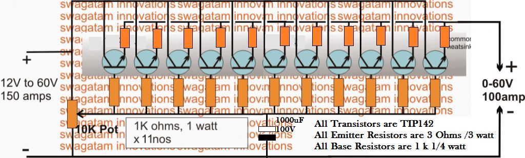
The design basically utilizes a common collector or an emitter follower topology for implementing the operations, by incorporating just a few Darlington power transistors, some resistors and a pot for varying the output voltage.
As can be seen in the diagram, the collectors and the emitters are all joined in common across each other while the bases are made into a common line via individual limiting resistors.
The free ends of these resistors are joined together with a pot across the negative line of the circuit, which determines the voltage regulation at the output of the circuit.
For acquiring more current, more number of transistors may be added in the design, and for reducing the output amps, these may be simply deducted from the configuration.
For inputs above 50V the pot must be upgraded to a high wattage type to sustain the high voltage across its terminals.
All the power devices must be mounted over a common aluminum heatsink without any mica isolation, so that the dissipation is shared uniformly across all the devices and a thermal runaway situation is prevented.



Comments (121)
Wow, thank you Bro, it helps a lot…
You are welcome Ruel!
Hello. Thank you for this simple yet practical circuit.
We know that the base resistor is used to limit the collector current and is very necessary. But the question is, what is the need for the resistor in the emitter path? Suppose a current of 10 amps passes through each emitter branch. Considering the resistance of 3 ohms, the power dissipated on the emitter resistor will be 300 watts. How is this justified? Thank you for your attention.
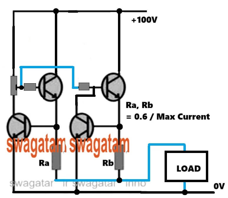
Yes, that’s right, in that case we can add a dedicated current limiter stage with each power transistors in the following manner, then the current limiter resistor values can be significantly minimized:
Hello, i am interested in designing a 240vac input 12vdc 150-200A load dependent power supply and this seems to be the place to get it figured out. All help is appreciated. Especially with the transformer selection portion. The project is actually converting 240vac 50hz to dc then using an automotive inverter to get 1500w 120v 60hz. I really want some lor coffee in europe and don’t want to ruin my 60hz machine with 50hz line. Thanks again.
Hi, thanks for your question.
I don’t think the inverter is actually needed, it appears to be an overkill.
Instead, you can simply use a 240 AC to 120 AC 1500 watt transformer for the required conversions.
Let me know if it makes sense.
No this does not make sense because i have ruined several appliances using step down transformers. Basically anything with a motor.
Hi, the transformer method is the best practice and the recommended method, because it will perfectly transform your 220V AC into 120V AC or vice versa.
However, you must ensure that the transformer wattage and voltage specifications are correctly matched with the load. Otherwise the voltage can drop causing problems with the working of the load.
I am sorry, I think I missed the frequency part. The transformer will not be able to transform the 50 Hz frequency into 60 Hz, which can be a problem to a inductive loads like motors.
The circuit is simple and effective
I have a problem with short circuit protection at 50V output.
It does not respond fast enough even if I limit the current at 2.5A
Even a relay current cut off circuit is to slow
The TIP142 blows instantly
Any recommendations?
Regards
Naude
You can add a current control feature to the above design as shown below. The current control transistor can be a 2N2222. Make sure to add a series 2.2K resistor with the potentiometer. The current limiting resistor RX can be calculated by solving the formula, RX = 0.7 / Max current.
Dear Swagatham,
In the given circuit bc547 is used. This is very low current BJT. Can we use transistors like 2N6287 (100 v(Vcb & Vce ; 20A Ic) or TIP 142 itself (10A Ic) ?
Dear Suresh,
I cannot see any BC547 in the above diagram, can you please specify which schematic are you referring to?
Sorry ? 2N2222 in the modified diagram with short circuit protection.
Maximum Collector Current |Ic max|: 0.8 A
The 2N2222 is configured as a current controller which has to handle only the base current of the TIP142 which is not more than 50 ma or maybe 100mA, so it can easy handle that.
Dear Swagatham, Thank you for the reply. I now understand the process. I was thinking that the 2n2222 (or its substitute) needs to handle the full load current (Say 10A). Anyways, I made a unit with two TIP142 in parallel and TIP 135C (25A) in place of 2N2222 you suggested. (may be I should try 2N2222). It works fine. The 10K gets a little warm. A wirewound pot may be a better choice , I think. I used 0.5ohm 25 watt resistance for Rx. There is some voltage drop when load is connected (tried a DC motor. it takes 0.335A and the voltage drops from 12 to 8.5. Do you think this could be improved ?
Thank you Suresh, Glad you understood the working of the current limiter stage and could successfully build the circuit.
With a 0.5 resistor for the current limiter resistor, the maximum load current would be restricted to:
I = 1.2 / 0.5 = 2.4 amps.
If your load is not consuming more than the above current then the voltage should not drop.
However, if the input current is lower than the load current requirement then the voltage will drop.
You can temporarily remove the current limiting stage and check whether the voltage is dropping or not, that will prove whether the current limiting stage is causing the voltage drop or not.
Dear Swagatham, Thanks a lot. on the test digital meter, it was showing only 0.335A. Let me check as you suggested. I also collected metal 2N2222 too just for testing and understanding the behavior of the circuit with both the transistors (2N2222 vs TIP 35C). plus a bigger cap too.
Thank you Suresh, for updating the info! Make sure your input current is optimal, as per the load requirements, otherwise the voltage will drop. All the best to you!
Dear Swagatham, Thank you.
One issue I noted with this is voltage creeping up or down. One needs to wait for some time for the voltage to stabilize. Then again one has to adjust since the voltage drops according to load.
Another thought ! can’t we use an opamp to control the output BJT / MOSFET ? will it not provide a better & safer control ?
[ I blew three TIP 142 today- investigating why this happened ].
Dear Suresh,
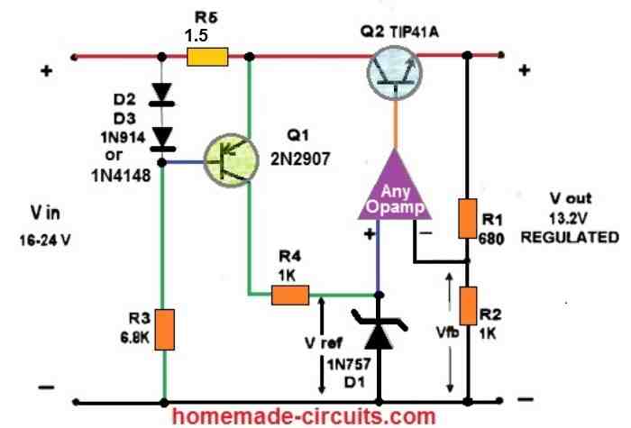
If the voltage drop is happening due to lack of current to the load, then even an opamp regulator will not be able to regulate it.
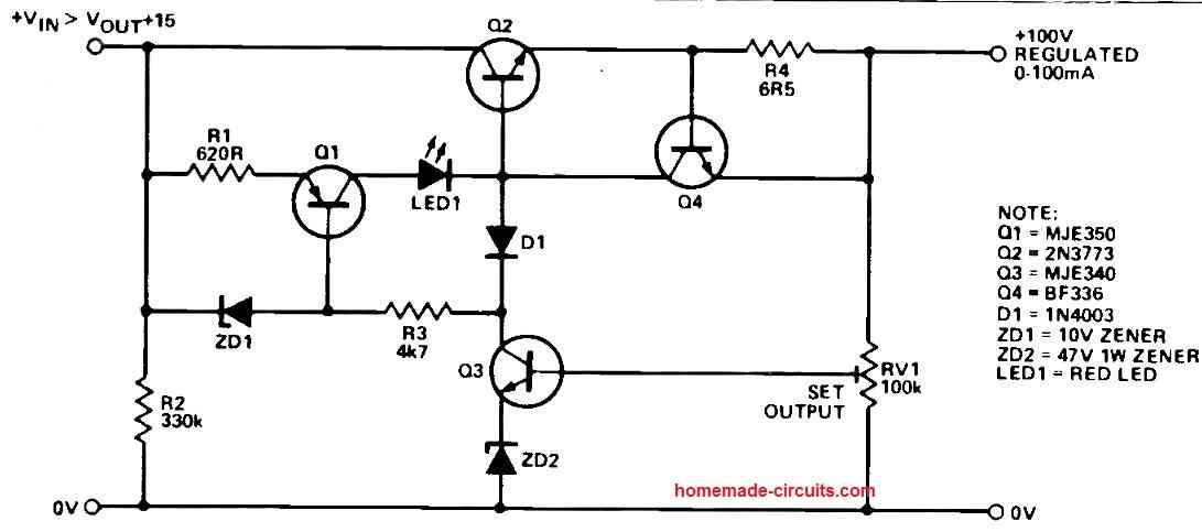
For an opamp based regulator you can refer to the following diagram:
For more details on transistor voltage regulators, you can refer to the following article:
https://www.homemade-circuits.com/simple-voltage-regulator-circuits-using-transistor-and-zener-diode/
Dear Swagatham,
“If the voltage drop is happening due to lack of current to the load,”
Oh no! I use a 65V 6 amp transformer..
thanks for the links. I shall check them.
This one looks very good. https://www.homemade-circuits.com/adjustable-0-100v-50-amp-smps-circuit/
OK, 6 amps looks quite adequate for your load, you can try the op amp version, if the current still drops then the problem could be with the transistor base resistor, which will need to be reduced further.
Dear Swagatham, Thanks for the suggestion. I was thinking the same. I shall check this.
You are welcome Suresh!
Thank you. Will try
I looks as if with the 2k2 there my output will only be 46V if my input is 56V and I need at least 50V max
OK, in that case put the 2.2k resistor in series with the wiper arm of the pot, just after the arrow head. This is actually to safeguard the 2N2222 current limiting transistor. However I think 2N2222 is rated at a maximum of 40 V, in that case you can use some other NPN transistor which can handle upto 100V.
Of coarse! I see. Thank you
I will report back
Hi
I had time to test the current limiting today
Like all the other methods it does limit current what it was designed for but on 50V with a dead short on the output it is just not fast enough and blows the darlington collector emmitor
Hi, maybe the current limiting resistor value was not appropriate, you can try increasing the value of the resistor, that might solve the issue. If not then it is unfortunate.
I am sorry to say that this is not a good circuit and its construction should not be recommended. Unbalance of collector current of transistors followed by thermal runaway is unavoidable
Emitter resistors are provided to avoid thermal runaway. The circuit may not be efficient but very easy to build and implement.
I am trying the 100amp power supply and it would not work , is they any one who got it to work
What kind of problem are you facing? Try with 10 amp first and check the response.
I am getting the same input voltage at the output and not adjusting, what I did to get it to work I place the input voltage on the base, and the base resistors on the collector and got a good variable voltage on the emitter but it cannot handle a load, it falls off from 13.8v to about 5v.
If the voltage is not adjusting then something might be be wrong with your transistor or the connections. Try with a small load at the output and check whether it is adjusting or not.
Hi Swagatam,
Good day to you. I am Manjunath. I have read your articles and the answers are good. I have a question that is how to convert DC 5Volts 3 Amp from the Battery pack of DC 12Volts 90Amp? Please give me your ideas for me.
2nd question is how to make a charger (Input AC ~220 Volts) for a Battery pack of DC 12Volts 90Amp.
Thank you Manjunath, for liking my articles.
You can probably try customizing the following circuit for boosting 5 V to 12V
You can adjust the number of turns of the coil to test the output response.
For the charger you can simply refer to the following article:
12V Battery Charger Circuits [using LM317, LM338, L200, Transistors]
Hi Swagatam,
I am asking about the buck converter from 12volts 100 Ah battery to 5v 3A., not for the boost converter. If you have any ideas on it please share them. You are only the person who can help me…Please help me on this.
Hi Manjunath,
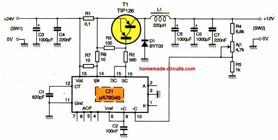
OK for a buck converter circuit you can customize the following circuit according to your own needs:
PWM Solar Battery Charger Circuit
If you have any further queries, please let me know.
Hi Swagatam,
I am always inspired from your post as they’re always helpful and great.
This circuit is interesting i want to test it as i have a SMPS 12v and 100amps. But one thing is confusing. In the given above circuit you used 11 transistor as each can bear 10A so overall 110A safe range for 100A.
If i connect my SMPS with it and for example voltage is decreased using the pot (given in your design) wouldn’t be the current at the output become high enough to blow transistors immediately.
I see that the circuit doesn’t have protection against overload and short circuit at the output. Please guide me if anything i can add or modify for it. Many thanks & Hats off always
Hi karan,
The number of transistors are actually not accurate, for 100 amp current there must be at least 20 nos of TIP142. More the numbers cooler will be the transistors.
The current through the transistors will depend on the load, not on the voltage adjustments. But yes wider input/output differential will cause the transistors to heat up a lot, that’s the drawback of all linear power supplies. To correct this, the input voltage range from the SMPS must be reduced appropriately.
Protection has not been provided, you can add a current limiting by adding a common 2N2222 limiting circuit network, as explained in the following concept.
2 Best Current Limiter Circuits Explained
Hi
I want to DIY Electroplating IGBT controlled full DC Rectifier 0-30 Volt DC and 500 Amp. Please help me out I saw some readymade circuit on Aliexpress but without full diagram
Hi, sorry, presently I do not have the requested circuit with me…
Hi Swagatam. I am searching a circuit which I can use as battery charger and as welding machine. I mean, by the primary of the transformer regulate the current and voltage. Where I can set up voltage for battery charger and charging current. I I need a welding machine use it with this application. Max voltage 40 or 48 and current from 30 to 1000.
Is it posible to design?
Hi Rafael, 30 to 1000 amp looks too high, and will require special mosfets to control the current….the transformer primary cannot be used for regulating the current.
If possible I will try to find a suitable circuit for you soon…
hello sir,
I need 5 volt dc and 100 amps power supply circuit diagram so please send me as soon as possible and send me your phone phone number for further conversation.
thanks
Hello Mohd, sorry I do not have a 5V 100 amp smps circuit with me at this moment…
how is this circuit going to give 100 amps, when you have 11 resistors in parallel of 3 w each, 10 amps makes more sense, but how is it going to pass 9 amps through a 3ohm resistor and dissipate 3 watts ???????
It is just an idea, you can customize it by reducing the resistor value, or add more number of transistors stage in parallel.
Looking for advice regarding a magnetiser I want to build for magnetising tachometer magnets. I would like to utilise the core of a welding transformer to wind a U shape electromagnet of 1500 turns which will carry 8 amps of current at 120V DC. The current will be switched on only for a few seconds at time to produce the magnetising field. I need a circuit for producing the 120V DC from a 240 V 50hz transformer. In that circuit I would like to use an SCR to turn on the current flow and have means of turning it off, either mechanically or electronically. Please advise if this is of interest to you,
You can try implementing the following design
I like to know more about this news letter
I assembled the circuit but the pot is extremely sensitive to any movement. When I connect a 12v motor and I set it to 12VDC output, the voltage drops to just over a volt using 22vdc battery as the supply voltage. Did I assemble incorrectly? I checked all the voltages across the TIP142’s, and all the voltages are almost the same in reference to ground. By the way, the motor works fine just using the battery. I need to make this circuit work so that I can connect multiple devices to a battery set and make sure all the current is drawn through the BMS. Thank you
What is the current of the motor? And how many TIP142 have you used?
Hello again Swagatam,
I’m building a power supply that will be 60v @ 20a. The transformer that I’m using after rectified and a smoothing cap is at 90v. It’s over a 1000va transformer. I want to get it regulated down to 60v. Would this circuit work with just a few TIP142s. I also have some 10k precision pots that are rated for higher voltage, but would probably end up using fixed value resistors. Or would you have a better solution.
Thanks, Ken
Hello Ken, yes, the above circuit can be used for the mentioned purpose….. for more info regarding the same and all the calculations you can refer to the following post:
How to Design a Stabilized Bench Power Supply Circuit
I would like to build a simple variable power supply with an input of 110 volt ac and an output variable voltage of approx. 1.5V to approx. 15V and a variable output current of up to approx. 100A
You will need an SMPS design for this, however I do not have this circuit with me at this moment
Hey there,
I am looking for a 8.1 100A buck converter. The power source is an Hp server power supply as seen here (https://www.ebay.co.uk/itm/HP-Proliant-1000W-Pwr-Supply-DL380-G5-DL385-G5-379124-001-HSTNS-PR01-403781-001/143648658961?hash=item2172209611:g:sw4AAOSwYxBemwUa)
Would this be possible. This will be used to charge a 3s2p supercapacitor. if possible Constant current and voltage.
Hey, can you provide the input voltage source specifications for the buck converter?
It’s 12v max 82A
You can try applying the following concept, but the transistors and the inductor will need to be heavily upgraded to handle 100 amps
PWM Solar Battery Charger Circuit
hello, i would like to ask if i can use this circuit to regulate the output of a 12v SLA battery to 100amp only? or less lets say 80amp. thanks.
do you have any circuit that can regulate sla battery current? thanks
You can use the following concept:
https://www.homemade-circuits.com/regulated-car-battery-charger-circuit-for-garage-mechanics/
You can replace the transformer with your battery, the output will produce a voltage and current regulated supply
Hi, no, the above circuit will regulate only voltage, not current.
Dear sir,
The request is , Quote “I would like to build a simple variable power supply with an input of 220/240 volt ac and an output variable voltage of approx. 1.5V to approx. 15V and a variable output current of up to approx. 100A.” Unquote.
If you clarify on following points i will be happy. The quote mentioned variable output current of upto 100A .Is the current variable in your circuit or it is fixed 100 A.
Where the input is to be connected, i think a separate 230 V Ac to 12 V Dc has to be wired separately?
In the above mentioned circuit, one is 150 A and other 100 A, what is 150A and 100 A. Why both outputs are given
Dear K premila,
The current is not variable, it will almost equal to the input current supply.
the circuit is designed to work with a 100/150 amp transformer.
The output is shown as 100amp to indicate that a minimum 100 amp can be achieved without fail with an input of 150 amp.
If you want to avoid the transformer, it may be possible by replacing all the BJTs with MJ10023 and by feeding a rectified/filtered 310V at the input side, this design being not isolated from mains this configuration can be dangerous to touch, so proceed with caution
Thanks for your clarification
Regards
Premila
you are welcome!
Ola Swagatam,
como faço para te enviar um arquivo para analise?
Olá Swagatam,
como posso enviar um projeto para analise?
Olá Swagatam,
Sou hobbysta e queria criar uma fonte de 70v como posso aumentar está.
poderia me mandar seu imail para enviar arquivos para analise.
Olá Swagatam,
Acompanho seu blog e estou aprendendo muito, tenho uma duvida relacionada a fontes ajustaveis.
Como posso ligar duas(2) fontes ajustaveis (paralelo ou serie) sendo que as duas tem potenciometros e regular a saida com um (1) potenciometro apenas?
Ficarei muito agradecido se puder me ajudar
Obrigado Joao, você pode dar um exemplo do design do circuito ao qual você está se referindo? Isso me ajudará a analisar o problema corretamente. No entanto, pode não ser tão fácil controlar as duas fontes que têm potes individuais a serem controlados com um único pote, você pode colocar um pote duplo e usá-lo simultaneamente para controlar as fontes juntas, para que seu requisito possa ser cumprido.
onde posso enviar um arquivo para analise?
João, se é um design pequeno, poderei analisar, mas os projetos maiores podem não ser possíveis por falta de tempo … você pode enviá-lo para
homemadecircuits
@gmail.com
can you teach me how to do circuit diagram 5volt 300 ampere..
I am going to try it and let you know. I have two more questions for you. The values for the pot and resistors are the same for the darlington pair? Do you think that it would be possible to drive the base of the the transistor or the darligton pair from a different power supply? 5v for the transistor or 10v for the pair? Sorry if questions sound a bit silly but electronics are a really new thing for me.
as mentioned earlier the values can be 100K for the pot and 47K for the base resistors of the Darlington pair using BU and MJE
you can drive it from a different low voltage source in that case the resistors and the pot could be exactly as suggested in the diagram.
if you are using a different supply then make sure that its negative is connected and made common with the load negative
Hello Swagatam.
I am trying to make a test bench for ac/dc motors and solenoids with a voltage range from 12 to 220VAC and VDC.The setup is a multiple output transformer,a selector switch, some relays and a high voltage rectifier with 2 different filters. One for 12V-50V and one for 110-220V.
For adjusting the voltage(5V in the 12V range up to 45 in the 220V range I am using a voltage divider). The problem is that because the type of loads I am testing have a small resistance the voltage drop is very high. I have to use a 1000kΩ resistance in series with the load to keep the drop in check. As you can see this not efficient and its bad design altogether.
I am thinking that if I used this desing using a couple of BU931p npn I have availaible it would do the trick.
Do you think it would work and if you do can you help my with the valueus of the resistor and the potensionmeter?
Hello Mike,
technically it should work, you can try it with some caution.
you might have to make the BU transistor more efficient by converting it into a Darlington pair, using a MJE13005 with it.
for the pot you could try a 100K pot and for the base a 47k 10 watt resistor.
Thank you very much for reply……….
I used 4 tip142 as per above circuit for 30amp o/p. I get o/p, but heat dissipated is more, because of that after sometime ciruit gets bypassed.
If I used IRF540 same manner, how do I connect?
Should I replace Collector of TIP142 to DRAIN of IRF540, Base of TIP142 to SOURCE OF IRF540 & Emitter of TIP142 to GATE of IRF540?
you must use a common heatsink that should be sufficiently large in order to keep the devices cool. you an also try adding one more TIP for the same.
for the mosfets the drain will correspond to collector, gate to base, and source to emitter
hi Swagatam,
Can I use IRF540 instead of TIP142, for above voltage regulator circuit??
Hi Kaustubh, you can try it…I think it might work, although BJTs are more suitable for this application
Hi again Swagatam
I would like to use the above circuit (with the Tip 32's ) @ 70 Amps with a 60V output transformer that when rectified and smoothed drops to 35V drawing 70 Amps. My goal output voltage is 24V i will be using 20 Tip 32's with 0r1 10W sharing resistors what do you think the 10K pot wattage should be and how good do you think that the output voltage regulation will be ( i also have the option of using Tip 3055's as well )
regards kev
yes that will do, the resistors and the pot can be the standard ones.
Sorry not certain where i got that from i meant Tip142 as in your circuit.
Hi Kev, TIP32 will not work since it's a PNP, and not a Darlington type of BJT, and moreover it's max current is less than 5amps…
Or suggest me a better 0 to 30 V variable power supply with 0 to 10 A variable current range..
i need 300 W power output at 30 V so a current of 10 A is required.
i prefer a simple design with less components..
can i use power transistors like TIP32 instead of 2N3055 ?
RT, the suggested link in the previous comment is probably the best design according to me and should provide you with the intended results, and it uses just a single IC so it won't be difficult to build.
TIP32 is less powerful than 2N3055 so they cannot be interchanged
hello sir RT again..
Could you please suggest a variable power supply circuit which can deliver voltage in the range 0 to 48 V and current in the range 0 to 25A
my transformer is a 300 W step down transformer having a total of 5 terminals in primary and 4 terminals in secondary…the transformer is able to output these voltages at different terminal connections ; 12 V, 24 V , 35V and 48 V
since the transformer is a 300 W one I assume a current delivery minimum of 22 A at 12 V , 11 A at 24 V, 8A at 35 V and 5A at 48 V…. so i require a circuit whose voltage can be varied from 0 to 48 and current from 0 to 25A.. the voltage and current have to be varied independently..
CAN I make the circuit with only one LM317 for voltage regulation and some current boost as shown in this blog page ?
https://www.homemade-circuits.com/2015/12/lm317-with-outboard-current-boost.html?m=1
Hi RT, you can try the last circuit using the 317/mosfet version….but the current cannot be made variable in this option, rather you could try the following design and modify the power transistor and the limiting resistor values for the desired customization.
https://www.homemade-circuits.com/2016/01/universal-variable-power-supply-circuit.html
Hello Sir.
If i short circuit the output, can i use this design like a dummy load for test linear PSU?
Hello Cesar,
if you short circuit the output of the above shown circuit, will result in blowing off the transistors, so I don't think that would be safe.
Hi Swagatam,
I made this circuit as it is shown. At first, it worked pretty well but managed to blow out a few TIP142 in a while.
I changed those and tried again, but yet it blew off a couple more. What am I doing wrong here? While mounting the TIP142s I am using thermal compound between the transistor and the sink.
Also I have a fan for active cooling of the heat sink.
Please suggest what may be wrong here.
Thanks
It’s because the proposed circuit is a recipe for disaster, it’s basically an amplifier without negative feedback, probably ringing in the AM spectrum, this should incorporate at least an OPamp to measure the output voltage and compare it to a reference preferably a constant current circuit, also whenever you connect several power transistors in parallel you need to use equalization resitors in the emitters (check any high power audio amp circuit) since it’s impossible to find 2 transistors with the same gain! maybe it will be simpler to just amplify the output of an LM317.
Hi VM, th above circuit can blow of only under two conditions, if the transistor pinouts are wrongly connected or there's an overload across the emitter/ground of the system.
you can try connecting 0.3 ohms 5 watt or some other lower value resistor (calculated) with the emitter of each of the transistors and then check the response.
you can use this formula to calculate the resistors.
R = V/10
Hi Bro,
Thanks for your reply.
Regarding the output voltage from the transformer, before I went about reducing the turns to get 26 volts unrectified from the secondary, I attached an AC Dimmer at the input of the primary coil.
Without the dimmer, the secondary was putting out 37 volts unrectified.
After using a dimmer on the primary as a simple trial, I could dial down the secondary unrectified voltage to up to 16 volts.
But after rectification and filtering through 15000 uF, 50 volts capacitor, the output remained steady at 50 volts DC (Rectified and filtered).
I tried 26 volts and lowered to the minimum limit possible of 16 volts unrectified from the secondary. No matter what the unrectified voltage was at the secondary, the capacitor being 50 volts, it constantly put out 50 volts DC when no load was attached. As soon as a load was attached, the DC voltage came down as per the limit set.
My question is that I intend to connect the LM723 voltage regulator circuit to the DC output of the transformer, and even at 20 volts at the secondary, the rectified and filtered output of the trafo is 50VDC without load, would this damage the LM723 chip? (LM723 datasheet states max input voltage as 40 volts).
Would connecting the LM723 circuit ACT AS A LOAD to the trafo and bring down the dc volt from 50 VDC to required 35 – 37 VDC? (Considering the secondary is set to 25 volts)?
Or do I need to change the filter capacitor to a lower voltage value of 40 volts so that the unloaded constant DC out is reduced to 40 volts?
Any other suggestions from your end would be welcome bro.
Thanks,
…the capacitor voltage rating indicates the maximum breakdown limit of the caapcitor, it has no connection with the output result
Bro, the AC dimmer has no role here so it must not be included. The 26V when connected to a bridge and a filter capacitor (with any voltage rating higher than 40V) and powered with a 220V input…the output should show a result as given below:
Peak V = 26 x root2
= 26 x 1.41
= 36.66V
you can connect a 10K 1/4 watt resistor across the output and check the response, the 50V should come down to the above calculated value.
Hi!
Thanks for your reply.
In the first circuit in my given link, using LM723, it is mentioned that this power supply is rated for 10 amps, while there are 4 x 2N3055 power transistors used. Each 2N3055 is rated for 15 amps. Does this make the circuit capable of 60 amps? If not, how many transistors should I use for 40 amps?
Also can I replace these transistors by any other suitable higher amp transistors or mosfets to make the circuit more efficient and less prone to heat related failures? Also this could reduce the no. of components used.
Regarding the pot used for current limiting, does this have to be a special kind of pot? Or any normal pot would do?
Awaiting your comments.
Thanks for all your help.
Regards,
Vimal
…15000uF/50V is great…although a higher voltage than 50V could be preferred for better safety
Hi,
Using an 1500 watt dimmerstat to step down a 50V trafo is an overkill….the right approach would be to tell the transformer maker to reduce a few number of turns and make the secondary voltage to 26V.
This 26V when rectified and filtered would yield roughly around 37V, the right value for your need.
I am not sure about the resistor wattage, you may have to fix it with trial and error, and by checking how much the selected one heats up….then increase the wattage until the dissipation looks manageable.
you can certainly share my website anywhere you feel so 🙂
Regards.
Hi !
Thank you so much for all your help. Really do appreciate your time and efforts put in to helping all.
I have a few more queries for the power supply incorporating LM723.
Got the transformer for feeding the LM723. I had ordered the transformer maker to make the transformer so that the input Primary is 230 VAC mains and output voltage is 35 – 37 volts DC.
The transformer which he made has an output of 51 volts dc without any load. He said that this would come down to 37 volts when load is connected.
If tuning down of the primary AC input voltage is required, the transformer maker has suggested using a 1500 watt AC dimmer, this in turn would tune down the output DC voltage. Is this ok to use for this circuit?
The LM723 has max input voltage of 40 volts dc. Would connecting this transformer with output of 51 volts DC (Unloaded) damage the IC? Do I need to tune down the voltage to below 40 volts dc without the load for feeding the LM723?
2) Do I need to use emitter resistors of 5 watts with TIP35C?
3) For smoothing capacitor used with the diode bridge on the transformer, I am currently using 15000 uF, 50 volts capacitor. Is this sufficient or do I need a different value? The transformer is rated for 37 volts dc , 40 amps.
Thanks again for all your help bro.
Also, do I have your permission to promote your blog on some of the technical facebook groups that I am a member of?
Awaiting your reply.
Regards,
Vimal
If the emitter resistors are removed then it be able to handle 60amps.
you can use the shown set up for gettinh 40 amps, replace the BD139 with a TIP122 for increasing amp response.
2N3055 can be replaced with TIP35C, and just 2nos can be used for getting 40 amps.
the pot can be any ordinary type.
Hi Swagatam!,
I need to make a bench power supply with the following parameters :
1) Input : Mains voltage 220 volts
2) Output : Adjustable regulated voltage up to 35 – 40 volts dc.
3) Current : Adjustable current up to 35 – 40 amps.
I have found a couple of circuit diagrams on the web, I am not sure of their correctness or performance parameters. Below please find the google drive link for the same.
https://drive.google.com/file/d/0B7h83BRbOTR0UnZ1X29lUzVTY1U/view?usp=sharing
Could you please help with the required circuit? Also it would be nice, if you could specify the transformer details for use with this circuit.
Thanks for your help.
Vimal
Hi VM,
It looks OK to me!
The transformer should be a 0-30V/40 amps.
ok sir thanks. but if it is told to use only 12v trafo, then whats the use of 12v dual type trafo rated like 12-0-12…? suppose i need a 12v psu and need to use trafo. i have trafo of 12-0-12 on secondary. do i need to use all 3 wires or just any 12v and ov wire? why is there 2x 12v out on single trafo?
thanks for clearing. 🙂
12-012V has its own advantages, depends on the application needs, which might specifically require and call for a 3 wire transformer….
for a 12V application you can select the center and any one of the outer wires ….however always buy a two wire transformer for such applications, meaning a transformer with only 0-12V wires, this will ensure better efficiency and higher current.
Sir, i have question regarding step down transformers. i saw many types of transformers at market. those have 2 wires at primary and 3 wires at secondary. im confused about that secondary part. suppose, that trafo is rated 12v 5A. but when i measure with dmm all 3 wire at one, i get more then 28v. now if theres a schematic told to add 12 v trafo, which wire should i connect? and whats the use of that center tapped wire? will you please clarify this please?
Thanks.
the center wire can be considered as the zero terminal, while the other two at the rated value of the transformer….so suppose we have a trafo rated at 12-0-12 this means when voltage is measured across any of the outer wires with respect to the center then it will indicate 12V….but if measured from end to end then it would show as 24V
Extremely nice idea. Albeit missing automation, if I may criticize like a noob. But the uniqueness of the idea outweighs that. I've never come across transistors being driven like that before. Before applying it however I would test the resistance values driving the transistors and find the upper and lower safe and comfortable limits on the pot in order to find a resistance value zone on it that does not make the transistors too hot for my liking. These values may also change a little if we add enough of more transistors to handle all the amps. Two thumbs up bro.
Thanks Mooney,
the above circuit can be made fully automatic by adding the following design to it:
https://www.homemade-circuits.com/2012/08/make-this-48v-automatic-battery-charger.html
The output of the above 100 amp power supply can be integrated with the input of this circuit for getting the required auto cut off feature.
The base resistors for the above 100 amp circuit may be increased to 10k 1 watt, and it would still work nicely since the transistors are all Darlington and have huge hFe values.
foarte util
thank you!