• Skip to main content
  • Skip to primary sidebar

Homemade Circuit Projects

Need circuit help? Post them in the comments! I've answered over 50,000!

Blog | Categories | About | Contact | Calculators-online
You are here: Home / Lamps and Lights / 0.6V to 6V/12V Boost Converter Circuit Diagram

DIY Circuits | Learn Basics | Arduino Coding


0.6V to 6V/12V Boost Converter Circuit Diagram

Last Updated on January 17, 2025 by Swagatam 52 Comments

In this post I have explained how to make a 0.6V to 6V or 12V boost converter circuit using a single chip MC74VHC1G14, which uses under 1V to operate.

About the IC MC74VHC1G14

Normally, we all know that a silicon transistor would find it difficult functioning below 0.7V, unlike germanium counterparts which are capable of doing it with ease, however nowadays we don't often hear about these devices which have become quite obsolete with time.

The circuit discussed here uses an inexpensive Schmitt trigger NOT gate MC74VHC1G14 from the 74XX TTL  family which are designed to work with voltages well below 0.6V, to be precise even with as low as 0.45V. The device we employ is manufactured by Motorola.

The presented 0.6V to 6V boost converter circuit can be even modified to achieve upto 12V from a 0.6V source.

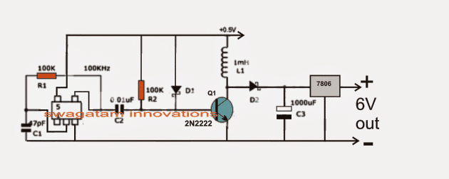
Referring to the figure below, we see a rather straightforward set up consisting of an oscillator stage using a single NOT gate inverter module as discussed above.


You can also try a Joule Thief Circuit for getting similar results.

Another design explains a 1.5 V to 3.6 V boost converter circuit


Circuit Operation

This NOT gate is very special since it's able to oscillate even at voltage as low as 0.5V which makes it very suitable for the present 0.6V to 6V or 12V boost converter application.

The oscillation frequency here is determined by R1 and C1 which is calculated to be around 100kHz.

The above frequency is fed to the base of an NPN transistor for the required amplification.

C2 makes sure the two IC and the BJT stages are kept isolated from direct contact in order to avoid the low input voltage from dropping below 0.5V

R2 and thee schottky diodes D1 keeps the BJT sufficiently biased for helping an optimal oscillatory response for the transistor.

D2 is another schottky diode which is introduced to keep the charge from C3 disconnected during the switch OFF periods of Q1 otherwise the stored charge inside C3 could get discharged or shorted via Q1.

The IC 7806 at the output is to maintain a fixed 6V irrespective of the boost level created by L1 and the associated converter stages.

L1 must be wound strictly over a ferrite core. The dimension and data of the coil is a matter of some trial and error or it may be procured as a ready made unit for the same.

Circuit Diagram

0.6V to 6V/12V Boost Converter Circuit Diagram

You'll also like:

  • transformerless LED automatic lampSingle Ended nOOds, 300mm long Flexible LED Filament, Warm White 3V
  • dynamo2BchargerRechargeable LED Lantern Circuit Using Dynamo
  • LEd connections compressedSimple LED Circuits
  • OneTransistorLEDFlasherCircuitDiagram2CImageSingle Transistor LED Flasher Circuit

Filed Under: Lamps and Lights Tagged With: 12V, Boost, Converter

About Swagatam

I am an electronics engineer and doing practical hands-on work from more than 15 years now. Building real circuits, testing them and also making PCB layouts by myself. I really love doing all these things like inventing something new, designing electronics and also helping other people like hobby guys who want to make their own cool circuits at home.

And that is the main reason why I started this website homemade-circuits.com, to share different types of circuit ideas..

If you are having any kind of doubt or question related to circuits then just write down your question in the comment box below, I am like always checking, so I guarantee I will reply you for sure!

Previous Post: « Fishing YoYo Stop-Motion Switch Circuit with Indicator
Next Post: Making a “Helping Third Hand” for Aiding Soldering Jobs »

Reader Interactions

Comments

Arpan ASR says:
June 21, 2014 at 12:02 am

HI bro,
If i use 7805 inserted of 7806..than it use as a smartphone charger..??

Reply
Swagatam says:
June 22, 2014 at 8:32 am

Hi bro, both will work and can be used according to me.

Reply
Back to Newest

Need Help? Please Leave a Comment! We value your input—Kindly keep it relevant to the above topic! Cancel reply

Your email address will not be published. Required fields are marked *

Primary Sidebar

circuit simulator image


Subscribe to get New Circuits in your Email


Categories

  • Arduino Projects (93)
  • Audio and Amplifier Projects (133)
  • Automation Projects (17)
  • Automobile Electronics (101)
  • Battery Charger Circuits (85)
  • Datasheets and Components (109)
  • Electronics Theory (149)
  • Energy from Magnets (27)
  • Games and Sports Projects (11)
  • Grid and 3-Phase (20)
  • Health related Projects (27)
  • Home Electrical Circuits (13)
  • Indicator Circuits (16)
  • Inverter Circuits (95)
  • Lamps and Lights (159)
  • Meters and Testers (71)
  • Mini Projects (28)
  • Motor Controller (68)
  • Oscillator Circuits (28)
  • Pets and Pests (15)
  • Power Supply Circuits (91)
  • Remote Control Circuits (50)
  • Renewable Energy (12)
  • Security and Alarm (64)
  • Sensors and Detectors (106)
  • SMPS and Converters (34)
  • Solar Controller Circuits (60)
  • Temperature Controllers (43)
  • Timer and Delay Relay (49)
  • Voltage Control and Protection (42)
  • Water Controller (36)
  • Wireless Circuits (30)


Other Links

  • Privacy Policy
  • Cookie Policy
  • Disclaimer
  • Copyright
  • Videos
  • Sitemap


People also Search

555 Circuits | 741 Circuits | LM324 Circuits | LM338 Circuits | 4017 Circuits | Ultrasonic Projects | SMPS Projects | Christmas Projects | MOSFETs | Radio Circuits | Laser Circuits | PIR Projects |

Social Profiles

  • Twitter
  • YouTube
  • Instagram
  • Pinterest
  • My Facebook-Page
  • Stack Exchange
  • Linkedin


Recent Comments

  • Swagatam on Arduino 2-Step Programmable Timer Circuit
  • Swagatam on Simple Buck-Boost Converter Circuits Explained
  • Swagatam on IC IR2111 H-Bridge MOSFET, IGBT Driver IC: Full Datasheet, Circuit Diagram
  • Swagatam on Electronic Circuit Projects, Tutorials, and Practical Engineering Solutions
  • Kadir on Simple 3 Phase Inverter Circuit

© 2026 · Swagatam Innovations