• Skip to main content
  • Skip to primary sidebar

Homemade Circuit Projects

Need circuit help? Post them in the comments! I've answered over 50,000!

Blog | Categories | About | Contact | Calculators-online
You are here: Home / Electronics Theory / Calculating Capacitor Charge/Discharge Time using RC Constant

Calculating Capacitor Charge/Discharge Time using RC Constant

Last Updated on April 1, 2020 by Swagatam 4 Comments

Capacitor charge and discharge periods is usually calculated through an RC constant called tau, expressed as the product of R and C, where C is the capacitance and R is the resistance parameter that may be in series or parallel with the capacitor C. It may be expressed as shown below:

Table of Contents
  • Cutoff  frequency

τ = R C

RC 2

The RC constant tau may be defined as the period required to charge a given capacitor through an associated series resistor by a difference of approximately 63.2% between its initial charge level and the final charge level.

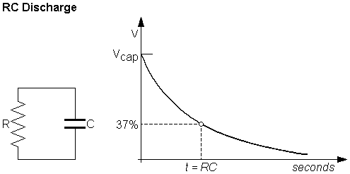
Conversely, the above expressed RC constant may be defined as the period required to discharge the same capacitor through a parallel resistor until 36.8% of the charge level is left.

The reason behind setting these limits is the extremely sluggish response by the capacitor beyond these limits which causes the charging or discharging processes to almost take an infinite amount of time to reach the respective full charge or full discharge levels, and therefore is ignored in the formula.

The value of tau is derived from the mathematical constant e, or

1-e^{{-1}},

and to be more precise this may be expressed as the voltage required for charging the capacitor with respect to the parameter "time", as indicated below:

Charging

V(t) = V0(1−e^−t/τ)

Discharging

V(t) = V0(e^−t/τ)

Cutoff  frequency

The time constant

τ

tau is also typically associated with an alternative parameter, the cutoff frequency fc, and may be expressed by the formula:

τ = R C = 1/ 2 π f c

rearranging the above gives:, f c = 1 / 2 π R C = 1/ 2 π τ

where resistance in ohms and capacitance in farads yields the time constant in seconds or the frequency in Hz.

The above expressions may be further understood with short conditional equations, for example:

fc in Hz = 159155 / τ in µsτ in µs = 159155 / fc in Hz

Other similar useful equations are represented below which can be used for assessing a typical RC constant behavior:
rise time (20% to 80%)

t r ≈ 1.4 τ ≈ 0.22 / f c

rise time (10% to 90%)

t r ≈ 2.2 τ ≈ 0.35 / f c

In certain complicated circuits that may accompany in excess of one resistor and/or capacitor, the open-circuit time constant approach happens to offer a way of deriving the cutoff frequency by analyzing and calculating the total of many associated RC time constants.

You'll also like:

  • 1.  What is IGBT: Working, Switching Characteristics, SOA, Gate Resistor, Formulas
  • 2.  Understanding MOSFET Safe Operating Area or SOA
  • 3.  How Mosquito Traps Work
  • 4.  6 Simple AC Bridge Circuits Explained
  • 5.  Basics of Strain Gauge Measurements
  • 6.  How Varactor (Varicap) Diodes Work

About Swagatam

I am an electronics engineer with over 15 years of hands-on experience. I am passionate about inventing, designing electronic circuits and PCBs, and helping hobbyists bring their projects to life. That is why I founded homemade-circuits.com, a website where I share innovative circuit ideas and tutorials. Have a circuit related question? Leave a comment.... I guarantee a reply!

Previous Post: « How Stepper Motors Work
Next Post: RPM Controller Circuit for Diesel Generators »

Reader Interactions

Comments

  1. Hossein says

    April 16, 2025 at 11:38 pm

    Hello, I am studying at Mohajer University of Isfahan. Our professor has asked for tr analysis from 10% to 90%!! How to get tr = 2.2RC
    can you write in a sheet an send to my email . thanks
    [email protected]

    Reply
    • Swagatam says

      April 17, 2025 at 8:27 am

      Hi, here’s the answer to your question:

      When a capacitor is charging through a resistor, then the voltage across the capacitor increases gradually from 0V to the final voltage Vf.

      The equation for the voltage across the capacitor at any time t is:

      V(t) = Vf × (1 – e^(-t / RC))

      Now we want to find how much time the capacitor takes to charge from 10% of Vf to 90% of Vf. This is called as rise time denoted by tr.

      So:

      At time t1, the voltage is 10% of Vf:

      0.1 = 1 – e^(-t1 / RC)
      => e^(-t1 / RC) = 0.9
      => -t1 / RC = ln(0.9)
      => t1 = -RC × ln(0.9)

      At time t2, the voltage is 90% of Vf:

      0.9 = 1 – e^(-t2 / RC)
      => e^(-t2 / RC) = 0.1
      => -t2 / RC = ln(0.1)
      => t2 = -RC × ln(0.1)

      Now subtract t1 from t2 to get tr:

      tr = t2 – t1
      = RC × [ -ln(0.1) + ln(0.9) ]
      = RC × ln(0.9 / 0.1)
      = RC × ln(9)
      = RC × 2.2

      So now finally we get:

      tr = 2.2 × R × C

      Reply
  2. suat says

    December 7, 2023 at 1:39 pm

    Hi Mr Swagatam;
    If the subject is smps circuit and input 220V AC output 72V Dc battery charger. We see high voltage about 320V and double high voltage capacitors at the primary side (each has about 160V). When there is no load we will apply input voltage for a while and then unplug it. In that case it is possible to say about the voltage and time value grapic untill they discarge in bold outline.

    Reply
    • Swagatam says

      December 7, 2023 at 2:37 pm

      Hi Suat,
      You can find the capacitor discharge graph online, you will be able to see that the charge exponentially keeps declining but never reaches zero.

      Reply

Need Help? Please Leave a Comment! We value your input—Kindly keep it relevant to the above topic! Cancel reply

Your email address will not be published. Required fields are marked *

Primary Sidebar

Subscribe to New Circuit Ideas

Categories

  • Arduino Projects (87)
  • Audio and Amplifier Projects (132)
  • Automation Projects (17)
  • Automobile Electronics (101)
  • Battery Charger Circuits (83)
  • Datasheets and Components (104)
  • Electronics Theory (143)
  • Free Energy (37)
  • Games and Sports Projects (11)
  • Grid and 3-Phase (19)
  • Health related Projects (25)
  • Home Electrical Circuits (12)
  • Indicator Circuits (14)
  • Inverter Circuits (87)
  • Lamps and Lights (142)
  • Meters and Testers (69)
  • Mini Projects (46)
  • Motor Controller (64)
  • Oscillator Circuits (27)
  • Pets and Pests (15)
  • Power Supply Circuits (108)
  • Remote Control Circuits (50)
  • Security and Alarm (64)
  • Sensors and Detectors (101)
  • Solar Controller Circuits (59)
  • Temperature Controllers (42)
  • Timer and Delay Relay (49)
  • Transmitter Circuits (29)
  • Voltage Control and Protection (37)
  • Water Controller (36)

Calculators

  • Battery Back up Time Calculator
  • Capacitance Reactance Calculator
  • IC 555 Astable Calculator
  • IC 555 Monostable Calculator
  • Inductance Calculator
  • LC Resonance Calculator
  • LM317, LM338, LM396 Calculator
  • Ohm’s Law Calculator
  • Phase Angle Phase Shift Calculator
  • Power Factor (PF) Calculator
  • Reactance Calculator
  • Transistor Astable Calculator
  • Transistor base Resistor Calculator
  • Voltage Divider Calculator
  • Wire Current Calculator
  • Zener Diode Calculator
  • Filter Capacitor Calculator
  • Buck Converter Calculator
  • Boost Converter Calculator
  • Solar Panel, Inverter, Battery Calculator
  • Wire Current Calculator
  • SMPS Transformer Calculator
  • IC SG3525, SG3524 Calculator
  • Inverter LC Filter Calculator

People Also Search

555 Circuits | 741 Circuits | LM324 Circuits | LM338 Circuits | 4017 Circuits | Ultrasonic Projects | SMPS Projects | Christmas Projects | MOSFETs | Radio Circuits | Laser Circuits | PIR Projects |

Recent Comments

  • Swagatam on 2 Compact 12V 2 Amp SMPS Circuit for LED Driver
  • Alan Bishop on AC Motor Speed Controller Circuits using Back EMF
  • Swagatam on Real MPPT Solar Charger Circuit Using Arduino, LCD, and Manual/Auto Switch
  • Swagatam on AC Motor Speed Controller Circuits using Back EMF
  • Swagatam on DC to DC Converter Circuits using SG3524 [Buck, Boost Designs]

Company

  • Privacy Policy
  • Cookie Policy
  • About Me
  • Contact
  • Disclaimer
  • Copyright
  • Videos
  • Sitemap

Social Profiles

  • Twitter
  • YouTube
  • Instagram
  • Pinterest
  • My Facebook-Page
  • Quora
  • Stack Exchange
  • Linkedin
  • © 2025 · Swagatam Innovations