The high power "zener diode" circuit using transistor shunt regulator presented here can be used for obtaining a highly accurate, temperature and voltage stabilized outputs from high current sources, safely.
Normal Zener Limitation
The low power zener diodes that we normally use in electronic circuits are specified to work with low currents, and therefore cannot be used for shunting or stabilizing high current supplies.
Although higher rated zener diodes are available, these could be relatively expensive. Nonetheless, it is actually possible to make a customizable high power zener diode using a power transistors and a shunt regulator IC as shown below:
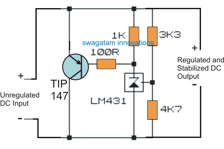
Circuit Diagram
Using a Shunt Regulator
Looking at the figure we can see the involvement of a specialized shunt regulator IC in the form of LM431 or TL431, which is basically a low power adjustable zener diode.
Apart from the variable voltage attribute, the device also includes the feature of producing a temperature stabilized output, meaning ambient temperature conditions is not going to influence the performance of this device, which is not possible with the ordinary diodes.
But as far as power handling capacity is concerned the TL431 device is no better than the conventional zener diode counterpart.
However when it is combined with a power transistor such as the shown TIP147, the unit gets transformed into a highly versatile high power zener diode unit, capable of shunting and stabilizing high current sources without getting damaged.
Example Application
A classic application example of this circuit can be visualized in this motorcycle shunt regulator circuit where the design is employed for shunting and safeguarding the motorcycle alternator from the high reverse EMFs.
The design can be also tried in high current capacitive power supplies for acquiring surge free stabilized output from these rather unsafe but compact transformerless power supplies.
Other suitable applications of this versatile circuit could be for controlling windmill outputs and as electronic load controller for regulating hydro-generators outputs.
Without the TIP147 integration, the LM431 stage looks pretty vulnerable, and also the regulation being developed only across the anode/cathode of the device rather than across the main supply terminals.
High Power Control
With the power transistor integrated the scenario changes completely and now the transistor simulates the shunt regulator's results, shunting the high current from the input to the correct levels, as specified by the LM431 configurations.
The potential divider made by using the 3k3 and the 4k7 resistors at the reference input of the IC essentially determine the triggering threshold for the IC, typically the upper resistor can be tweaked for getting any desired zener stabilized voltage output from the transistor circuit.
The detailed calculations for the resistors may be learned from this TL431 shunt regulator datasheet
Note: The TIP147 must be mounted on a substantially big finned type heatsink for enabling a proper and an optimal functioning of the circuit.


Questions & Answers
Hi,
How can I change 60vac to 5vdc?
I am using a double tap transformer.
I made a 1n40007 bridge rectifier, with a 470 micro Farrad electrolytic capacitor.
Many thanks.
James
Hi, you can convert 60V AC to 5V DC using a transistor circuit but the transistor will heat up a lot. Instead of using a 60V transformer you can use a 12V transformer that can be easily converted to 5V using an ordinary 7805 IC
Other alternative would be to use a buck converter circuit such as this:
PWM Solar Battery Charger Circuit
Hi Swagatam;
From the source 220 AC transformer to 22 AC after bridge diode I have used 12 V zener diode for 12 V 0.4 W fan. There also is a 1 K resistor between + source and diode (cathode) in the circuit but this resistor is overheating. I need your help-Regards
Hi Suat, it is happening due to high voltage difference between the input and the output, which is causing the resistor to handle a lot of current. To prevent this you can either increase the value of the resistor or decrease the voltage to 15V. However increasing the resistor value will proportionately decrease the output current to the fan.
Swagatam many thanks for the reply.
I think to give the details may be remedy for me and you to help me. Input transformer 220 AC / 22 DC / 33 DC(after capacitor included) Circuit will adjust / limit the output voltage and current by using LM317 / BD139 / TIP3055. However I need to add a fan for cooling (may be 12 V or 5 V) and lower voltage about 9 / 10 / 12 V for the digital volt / amp meter (with three cables / black/red/yellow). Kind regards.
You are welcome Suat, you can use a separate LM317 to create a DC for your fan and for the meter, because a zener diode cannot be used to drop 30V to 12V with 0.4 amps current for the motor and the meter.
As you advised to use separate LM317 is most reliable. However Fan is 0.4 W it is about 30 mA and digital meter is about 13 mA under 12 V. I also have tested and 9 V or even 8 V is also enough to run the digital meter display. So, in case fan and display in serial connected Please advise what LM317 output voltage should be? Or I should use separate connection of them to the circuit? Or may be I can try by increasing the voltage from minimum side. Regards
If you are connecting the 12V motor and 9V digital meter in series, then the meter 13mA might try to restrict the 30 mA of the motor and the motor might not be able to perform correctly. But still you an try it, and use a separate LM317 set at 12+9 = 21 V output.
Another option could be to use a 0.33uF/100V capacitor connected with the 22V AC from the transformer, and then rectify the low current AC from the capacitor using diodes, zener diodes and filter capacitor.
Hi!
How many Volts do that curcuit give me?
How many Amperes?
How do i change the resistors to a higher or lower Voltage?
Thanks!
Hi, output voltage will depend on the adjustment of the resistor values. Ampere can be adjusted by selecting the transistor appropriately. More info is provided here:
How Shunt Regulator TL431 Works, Datasheet, Application
Hello Swagatam:
thank you for all your efforts.
I would like to substitute the Transistor with a 2N6040 in the TL431 Transistor Zener Diode Circuit for Handling High Current Stabilization.
My bottom line is to look for a high precision trigger ( .1 Volt) for shunting lipofe cell when the charge goes above level I desire.
I also looked into the 2 transistor circuit…Battery Full Charge Indicator Circuit using Two Transistors… can I also modify this for making the same circuit with the same PNP darlington for making the high power shunt.
I would also assume any resistive load would be placed between the Collector and
the Negative side of the cell, limiting the current dumping to match the rating of the transistor.
Any recommendations would be greatly appreciated
Hello Lisa, May i know what is the source of the supply? If it is from an alternator or a solar panel then your shunt regulator assumption would be fine, but if it from a transformer, or an SMPS then a shunt system may not be recommended.
Hi.. I wanted to build Over Voltage Protection for a 32 amp Lithium Ion Phosphate battery being charged at 4 amp, in an 8 Serial connected cell configuration.,, Just need something precision for the cells. I thought the TL431 and a Darlington would give me a fine adjustment, and a quicker turn on,
Hi, yes it is easily possible using any of the standard battery charger circuits that I have posted in this blog, however for a series connected cells you may have to employ a balance charger, so that each of the cells are individually monitored and charged.
I have one such design available in this blog, you can check it out here:
Lipo Battery Balance Charger for Charging of Series Connected Lipo Cells
Thank you sir.
can I use a power zener diode instead. I searched for it, couldn’t find it online.
instead of zener alone you could try zener with an SCR, and use a high power scr as per the specifications for the shunting, as discussed here
https://www.homemade-circuits.com/scr-shunt-for-protecting-capacitive-led/
Suppose if I am using a flange resistor in series(let’s say 1000w, 500 ohm) with a zener diode in series will I be able to regulate my output to 12V.
my input is 160V 8A.
yes that’s possible but you will have to calculate the zener diode wattage and the resistor wattage correctly. A huge amount power will be shunted and dissipated in the form of heat in the process.
hello sir, Can I possibly make a voltage regulator to regulate 75V to 185 V to 12V.
Hello Gotham, yes you can but not through the above circuit, because the above circuit is built for controlling only output from AC alternators or dynamos