The article details a circuit design for controlling a washing machine motor agitator through a preset time sequence which also includes an alternate reversing of the motor rotation. The circuit was requested by Mr. E.Rama Murthy.
Technical Specifications
I am having old washing machine which is good working till now. Of late, its PCB has gone and I am not able to get it locally.
The mechanical/electrical working is good. The timer is electrical-mechanical and is working okay. What I need is a circuit or your made-item with the specifications as below.
It could work on 220 volt ac or I can provide 5Volt dc supply thru local power adaptor. The unit should have for operating of motor, 2 nos separate relays for running the motor forward and reverse.
The timing for the operations of relays is 2 secs stop and 5 secs forward and 2secs stop and 3 secs reverse. This is for working of clothes agitation process.
The motor is 0.5 hp. I should be able to enclose it in a box which is water-proof. Kindly let me know how much I should send you by way of bank transfer, which should include your packing and forwarding charges.
Thanking you in advance.
E.Rama Murthy., Visakhapatnam., A.P.
Understanding Washing Machine Motor Wiring
Before I have explained how to make a customized timer controlled washing machine unit, it would be important to learn the basic diagram of a 3 wire washing machine motor.
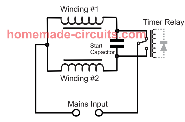
As shown in the below diagram, a washing machine motor typically has a couple of identical sets of winding. Unlike fan motor, the two winding are identical in terms of wire thickness and number of turns.
This is because a washing machine motor has to rotate in both ways. Meaning, it has to move anti-clockwise and clockwise alternately.
Therefore, the wiring is implemented in such a way that the each winding works like a main winding as well as capacitor start winding alternately, depending on which winding is selected by the timer relay.
How Reverse Forward Rotation is Implemented
In the image above, assuming the winding #1 is selected by the timer relay, causes the winding #1 to act like the main motor winding, while winding #2 works like a supporting capacitor start winding, for initiating the motor rotation in a specified direction.
Next, when the timer relay connects with the winding #2, this winding now becomes the main winding and winding #1 is used like a capacitor start winding for turning the motor in the opposite direction. In this way a washing machine motor is able to rotate in a reverse/forward direction despite of being an AC motor.
Designing the Circuit
The proposed washing machine motor agitator controller circuit functioning may be understood as I have explained below:
When power is switched ON to the circuit, pin15 of IC gets reset by C1, rendering a high at its first pin#3 which is the first pinout in the order of sequence for the IC 4017.
The above high logic at pin#3 instantly passes through C2 causing a logic high at the input of N1 which in turn causes a logic high at the output of N2.
The above situation keeps T2 and RL/1 switched OFF.
Now after a predetermined time of 2 seconds which can set by appropriately selecting the values of C2/R2/R3, C2 becomes fully charged rendering a logic zero at the input of N1 which instantly changes the states at the outputs of N1/N2 causing a logic zero at the output of N2 which in turn switches ON T1.
T1 passes a short positive pulse via pin#3 high across its emitter/collector to pin#14 of IC1.
The above pulse clocks IC1 so that the logic high pin#3 now shifts to the next pinout in the order, pin#2.
The above high at pin#2 identically passes on at the input of N3 rendering an instant low at its output. This low triggers T2 and RL/1 activating the motor in a particular direction depending on the wiring of RL/2 contacts.
N4 holds the above logic state until 3 seconds is lapsed which is determined by the values of C3/R7, after which N4 reverts its state switching ON T3, which causes a short pulse to pin#14 of IC1.
The above pulse once again clocks IC1 so that the logic now shifts from pin#2 to pin#4 in the order of the sequence.
Pin#4 high yet again repeats the first sequence which was implemented when the logic was at pin#3.
The above conditions deactivates RL/1 and the motor for another 2 seconds.
After the above 2 seconds has elapsed, T1 switches ON providing a pulse to pin#14 which results in the shifting of the sequence to pin#7.
The high at pin#7 yet again switches ON T2/RL1 and also RL/2. However this time the motor changes its rotational direction due to the activation of RL/2.
C4/R11 values make sure that the above condition stays ON for about 5 seconds. After 5 seconds T5 performs the clocking of pin#14 which shifts the sequence to the next pinout order that is at pin#10. Since pin#10 is connected to pin#15, the situation instantly bounces of and resets back to pin#3....and the cycle repeats.
Circuit Diagram
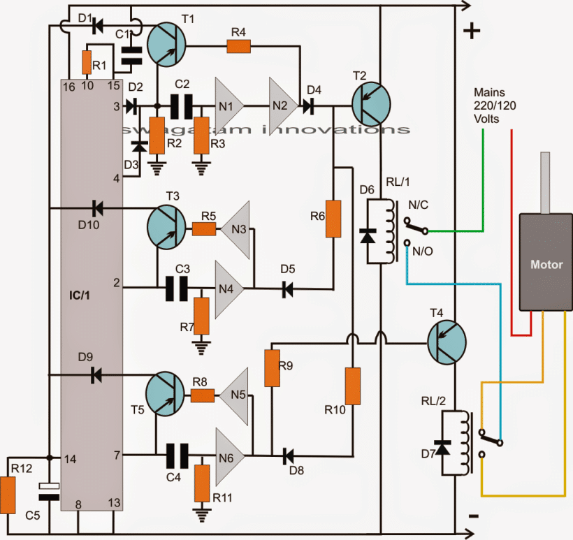
Parts List for the above washing machine controller timer circuit
- R1, R4, R5, R6, R8, R9, R10 = 10K
- R2, R3, R7, R11, C2, C3, C4 = TO BE DETERMINED BY TRIAL AND ERROR
- R12 = 100K
- C5 = 33uF/25V
- T1, T3, T5 = BC557
- T2, T4 = 2N2907
- D1----D10 = 1N4007
- N1----N6 = IC 4049
- IC1 = 4017
- RL/1, RL/2 = 6V/100mA RELAYS SPDT
How to Wire the washing machine motor connections.
As shown in the above diagram, the motor would have three wires, one of them would be the mains input while the other two for the flipping action or for reversing the motor directions.
You would want to take the help consult a qualified washing machine repair technician for confirming the exact wire inputs before connecting them with the circuit.


Comments
dear sir, i have problem to connect ic4049 as it has 16 pins then which 2 pins should i connect as per your circuit
can i use ic555 or any other instate of ic4017 as it is not available for me by few changes in circuit
no, that's not possible..
May be you are write but i think that a wish is more important then a degree to do something. If you are agree you will answer me.
you can try the above circuit, but if you get stuck somewhere or if it does not work then you won't be able to troubleshoot…..
sir, i am not an electric engineer i don't know how to connect ic 4049 would you tell me how to connect it ( from which pins i connect it ) please tell me. can i use another ic instate of ic4017 and ic4049 as it is not available in market
thanks
Hi Manish, I am sorry, If you are not reasonably expert with electronics then you must not try the above circuit because the circuit may involve and call for precise testing operations, adjustments and tweaks, until it finally serves the purpose….
the above circuit is quite similar to your application need, you can modify the part values slightly and use it for your purpose
will you draw a circuit for my washing machine motor that runs it 15 seconds forward then stop it for 5 seconds and then run it 15 seconds backward and then stop it for 5 seconds and repeat this cycle for 15 minutes continuously.
pls. help me.
thanks
Manish Gupta