• Skip to main content
  • Skip to primary sidebar

Homemade Circuit Projects

Need circuit help? Post them in the comments! I've answered over 50,000!

Blog | Categories | About | Contact | Calculators-online
You are here: Home / Audio and Amplifier Projects / Touch Volume Control Circuit

Touch Volume Control Circuit

Last Updated on October 26, 2021 by Swagatam 7 Comments

This touch volume control circuit has two touch pads which enable the user to increase or decrease the volume of an audio amplifier simply by touching the relevant touch pads.

Table of Contents
  • How the Circuit Works

The advantages of this solid-state volume control are: very long life due to the absence of any wear and tear, quick and easy finger touch control, and low distortion.

How the Circuit Works

The circuit works like an electronic attenuator, configured to sense and respond to finger touch on alternate touch pads. The FET T1 is wired to simulate a variable resistor, across a resistive divider network T1, R1.

touch volume
The FETs can be interchanged with any of these equivalents: BF256B, BF256C, BF348, BFT10A, 2N5397

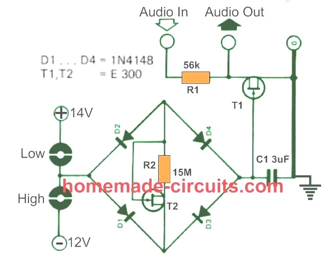
The resistance formed across T1 is determined by the negative voltage created across capacitor C1.

When the touch pads associated with the negative supply line is contacted with finger, a current via D2, R2 and D3 charges the capacitor C1, with a delay time decided by the values of C1, R2.

When the negative charge developed across C1 is sufficiently high, T1 is inhibited from conducting anymore, which allows an un-attenuated audio signal to pass through. This enables the volume to be increased

In order to reduce the volume of the audio, the user simply has to touch the pair of pads connected with the positive side of the supply.

This causes C1 to begin discharging, so that T1 again gets more conductive, and diverts the audio towards the ground line. This causes a corresponding amount of attenuation on the audio signal, and the volume gets reduced proportionately.

The amount of volume to be attenuated or increased will depend on the time for how long the touch pads are kept contacted with the finger.

The FET T1 simply behaves like a linear resistor whose gate bias is modulated by the audio signal input.

The output distortion is reasonably low as long as the input audio signal is not exceeded 30 mV level.

You'll also like:

  • 1.  100 Watt Amplifier Circuit Diagram using LM12 IC
  • 2.  60 Watt Amplifier Circuit
  • 3.  LM386 Amplifier Circuit [Working and Application Circuits]
  • 4.  Make this Crystal Radio Set Circuit using No Batteries
  • 5.  10 Useful Active Filter Circuit Diagrams Explored
  • 6.  Electronic Touch Organ Circuit

About Swagatam

I am an electronics engineer with over 15 years of hands-on experience. I am passionate about inventing, designing electronic circuits and PCBs, and helping hobbyists bring their projects to life. That is why I founded homemade-circuits.com, a website where I share innovative circuit ideas and tutorials. Have a circuit related question? Leave a comment.... I guarantee a reply!

Previous Post: « Loop-Alarm Circuits – Closed-Loop, Parallel-Loop, Series/Parallel-Loop
Next Post: Soft-Start Power Supply for Amplifier Loudspeakers »

Reader Interactions

Comments

  1. Oskar says

    March 10, 2021 at 6:13 pm

    Hello!
    What sort of pads do you use for the touch pads in the circuit? I’m planning to try and replicate it for fun and need to buy parts for it.

    Reply
    • Swagatam says

      March 10, 2021 at 7:34 pm

      Hi, they are simple copper pads, or copper tinned with solder pads

      Reply
      • Oskar says

        March 11, 2021 at 6:48 pm

        Alright, thank you!

        Reply
  2. Nelio says

    September 28, 2020 at 9:35 pm

    Hi Swag,
    I have a pair of wireless headphones that have the volume control kind of broken.
    When I roll it to increase or decrease the volume it some times faills to reproduce the sound in one of the sides and produces scratch sound.
    If I replace the volume with this circuit, will it work?
    Will I have a kind of a digital volume control?
    Best Regards.
    Nelio

    Reply
    • Swagatam says

      September 29, 2020 at 12:19 pm

      Hi Nelio, yes definitely you can replace the electro-mechanical one with the solid state type as explained above.

      It will provide a fully digital control without any losses.

      Reply
      • Nélio says

        September 30, 2020 at 1:05 am

        Hi Swag,
        Thanks.
        There’s only one catch with this circuit….
        The Voltage…. 12 and 14…
        The headphones are 3V (2×1.5V AAA Batteries)
        Best Regards.
        Nélio

        Reply
        • Swagatam says

          September 30, 2020 at 10:27 am

          Hi Nelio, that’s correct, so this circuit cannot be used for low voltage applications.

          Reply

Need Help? Please Leave a Comment! We value your input—Kindly keep it relevant to the above topic! Cancel reply

Your email address will not be published. Required fields are marked *

Primary Sidebar

Subscribe to New Circuit Ideas

Categories

  • Arduino Projects (87)
  • Audio and Amplifier Projects (132)
  • Automation Projects (17)
  • Automobile Electronics (101)
  • Battery Charger Circuits (83)
  • Datasheets and Components (104)
  • Electronics Theory (143)
  • Free Energy (37)
  • Games and Sports Projects (11)
  • Grid and 3-Phase (19)
  • Health related Projects (25)
  • Home Electrical Circuits (12)
  • Indicator Circuits (14)
  • Inverter Circuits (87)
  • Lamps and Lights (142)
  • Meters and Testers (69)
  • Mini Projects (46)
  • Motor Controller (64)
  • Oscillator Circuits (27)
  • Pets and Pests (15)
  • Power Supply Circuits (108)
  • Remote Control Circuits (50)
  • Security and Alarm (64)
  • Sensors and Detectors (101)
  • Solar Controller Circuits (59)
  • Temperature Controllers (42)
  • Timer and Delay Relay (49)
  • Transmitter Circuits (29)
  • Voltage Control and Protection (37)
  • Water Controller (36)

Calculators

  • Battery Back up Time Calculator
  • Capacitance Reactance Calculator
  • IC 555 Astable Calculator
  • IC 555 Monostable Calculator
  • Inductance Calculator
  • LC Resonance Calculator
  • LM317, LM338, LM396 Calculator
  • Ohm’s Law Calculator
  • Phase Angle Phase Shift Calculator
  • Power Factor (PF) Calculator
  • Reactance Calculator
  • Transistor Astable Calculator
  • Transistor base Resistor Calculator
  • Voltage Divider Calculator
  • Wire Current Calculator
  • Zener Diode Calculator
  • Filter Capacitor Calculator
  • Buck Converter Calculator
  • Boost Converter Calculator
  • Solar Panel, Inverter, Battery Calculator
  • Wire Current Calculator
  • SMPS Transformer Calculator
  • IC SG3525, SG3524 Calculator
  • Inverter LC Filter Calculator

People Also Search

555 Circuits | 741 Circuits | LM324 Circuits | LM338 Circuits | 4017 Circuits | Ultrasonic Projects | SMPS Projects | Christmas Projects | MOSFETs | Radio Circuits | Laser Circuits | PIR Projects |

Recent Comments

  • Swagatam on Understanding SG3525 IC Pinouts
  • Dan on Understanding SG3525 IC Pinouts
  • Swagatam on High Current Wireless Battery Charger Circuit
  • Swagatam on Timer Based Cell Phone Charger Circuit
  • Nitesh Agrawal on Timer Based Cell Phone Charger Circuit

Company

  • Privacy Policy
  • Cookie Policy
  • About Me
  • Contact
  • Disclaimer
  • Copyright
  • Videos
  • Sitemap

Social Profiles

  • Twitter
  • YouTube
  • Instagram
  • Pinterest
  • My Facebook-Page
  • Quora
  • Stack Exchange
  • Linkedin
  • © 2025 · Swagatam Innovations