In this article I have explained how to build a digital voltmeter and a digital ammeter combined circuit module for measuring DC volts and current through different ranges, digitally. Introduction Electrical parameters like voltage and current are inherently associated with electronics and with electronic engineers. Any electronic circuit would be just incomplete without appropriate supply […]
Circuits
7 Simple Continuity Tester Circuits Explained
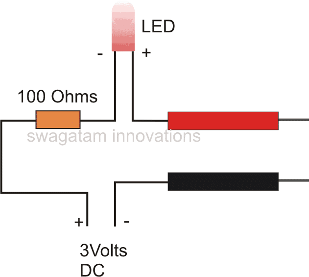
If you are looking for a simple circuit to test continuity of wires and long conductors, the explained 7 easy to build continuity circuits are the ones which you can try and might fulfill your requirement. What is a Continuity Tester A continuity tester is a device which is used for identifying the correct continuity […]
3 Frequency to Voltage Converter Circuits Explained
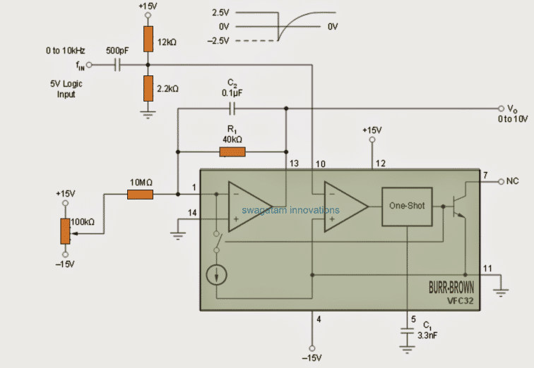
As the name suggests frequency to voltage converters are devices that convert a varying frequency input into a correspondingly varying output voltage levels. Here we study three easy yet advanced designs using IC 4151, IC VFC32 and IC LM2907. 1) Using IC 4151 This frequency voltage converter circuit using IC 4151 is characterized by its […]
Signal Injector Circuits for Quick Troubleshooting of all Audio Equipment
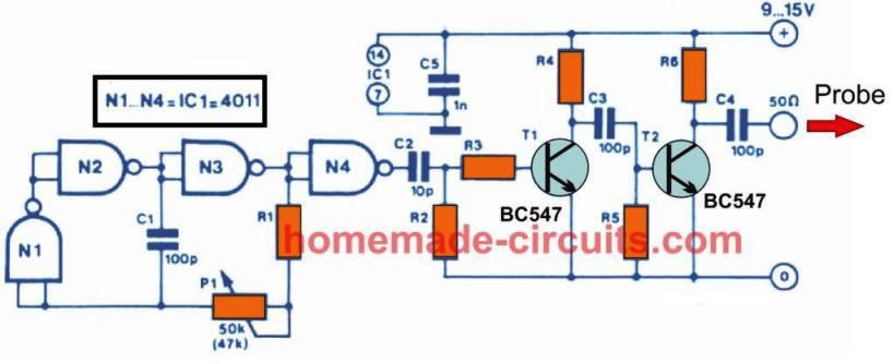
This simple signal injector circuits I have explained below can be accurately used for troubleshooting and alignment applications of all kinds of audio and high frequency equipment. 1) Using a Single IC 7400 One of the extremely handy devices for repairing audio and high frequency instruments is without question a equipment that will give you […]
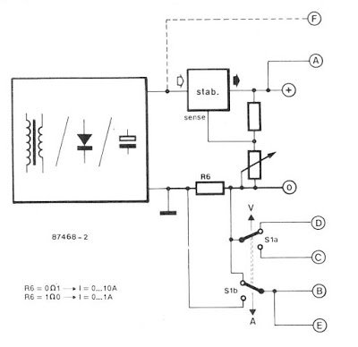
Simple Frequency Meter Circuits – Analogue Designs
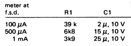
The following simple analogue frequency meter circuits can be used for measuring frequencies which may be either sine wave or square wave. The input frequency which is to be measured must be at least 25 mV RMS, for optimal detection and measurement. The design facilitates a relatively wide range of frequency measurement, right from 10 […]
4 Useful Logic Probe Circuits Explored
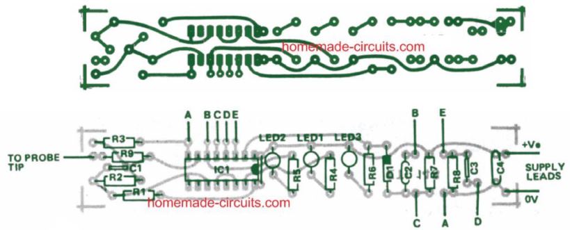
These simple yet versatile 4 LED logic probe circuits can be used to test digital circuit boards such as CMOS, TTL or similar for troubleshooting the logic functions of the ICs and the associated stage. What is a Logic Probe A logic probe circuit is a handheld electronic tool which can be used to test […]