Here I have explained how to build a solar inverter circuit for a 1.5 ton air conditioner (AC) for powering the AC during daytime directly from solar panels without depending on grid power. The idea was requested by Mr. Subhashish.
Main Specifications
A 1.5 ton air conditioner is equivalent to an approximately 1.5 x 1200 = 1800 watts load which is quite huge. In order to fulfill this formidable load the solar panel spec needs to be equally robust and rated with sufficiently high voltage and current specs.
Solar panels are generally rated at lower currents compared to their voltage ratings, which in turn heavily depend on the sunlight conditions. These parameters make these devices quite inefficient with their operations and managing their power optimally becomes a challenging task for the end user.
To tackle this, sophisticated controllers such MPPT solar charge controller are designed and can be effectively implemented for acquiring the maximum from solar panels, yet still calculating a solar panel for higher loads is never an easy job for any concerned technician.
A 1.5 ton air conditioner will probably require a 2000 watt solar panel, this value will need to be ascertained with practical experimentation.
The air conditioner will be normally a 220V or 120V operated device, and therefore the panel will also need to be rated at this voltage ideally in order to produce the most efficient results without using complex controller circuits.
This can be implemented by using 60V panels in series, which means 5 such panels would need
to be connected series, with each pane rated at 2000/300 = 6.66 amps, or practically a 10amp value would be just enough.
This voltage will be a pure DC, therefore this will need to be converted to AC for operating the air conditioner.
The conversion from DC to AC can be simply done by a using a full bridge inverter circuit as shown below:
Circuit Diagram and Description
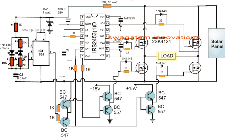
The IC IRS2453 enables the making of an efficient full bridge inverter circuit extremely easy. As can be seen the output of the IC just needs 4 N channel mosfets to be integrated for implementing a full bridge inverter actions.
The IC has a built-in oscillator, so no external oscillator stage is required for initiating the shown IRS2453 IC circuit. The Rt, Ct network associated with the IC determines the operating frequency of the inverter, and is supposed to be set at 50Hz or 60Hz depending on whether the operating voltage of the air conditioner is 220V or 120V respectively.
The IC 555 shown the left of the design is employed for generating a sine wave equivalent PWM feed for the full bridge inverter output.
The controlled PWM from the IC 555 is fed to the gates of the low side mosfets via the buffer transistor stage made through the BC547/BC557 pairs.
The above PWM feed helps the load to operate with an optimized RMS and alternating current which can be expected to be a close equivalent of the sinusoidal mains AC waveform.
The two pots associated with the IC 555 needs to be correctly adjusted until the required RMS and waveform is determined for the air conditioner.
Solar Panel Specifications
The 300V from the solar panel can be seen connected with the high side mosfet drains, which is stepped down to 15V through the indicated 33K, and 15V zener diode for providing a safe Vcc operating voltage for the two ICs.
Once the above procedures are implemented and appropriately set, the proposed 1.5 ton air conditioner can be effectively run throughout the day using only solar panels, without the need of any grid or utility power inputs.
Comments
Respected Swagatam hope you will be fine and doing great i am here to know what the 15v is all about where it goes thank you
Swagatam, thanks. But this circuit will produce Square wave not smooth sine wave, this may lead to rise in compressor temperature then to burn. right?
Alothman, you can replace the 555 PWM section with a PWM circuit, as presented in the following pages to get a smooth sinewave outcome…
https://www.homemade-circuits.com/2017/04/arduino-spwm-generator-circuit.html
https://www.homemade-circuits.com/2016/08/sg3525-pure-sinewave-inverter-circuit.html
MShah, it's for providing a 15V regulated DC supply to the ICs
Thanks again, just to be sure of the trafo , does it have to be 0-24V/330V to generate 220V?
330V is the peak voltage, 220V is the RMS….to make it simple you can use any standard step-down transformer rated at 24V/5amp/220V
Hello Swagatam
Just this one question, I have got 0.37 KW Submersible Pump AC 220V Single Phase .
Thinking of using the above circuit
The Pump rated current is 0.37KW
Pump Input Voltage 220 VAC Single Phase
I plan to use the above circuit with a 36V Panel 720 Watt
Will it be sufficient to run as long as there is sun
Thanks in advance
Hello Lufono, yes it will be enough to run it almost as long as sun is present.
you will need a 0-24V/330V transformer connected across the "load" points of the inverter circuit for generating the required 220V from the 36V input.
hi sir,if iwant to use this circuit for higer wattage ie 4000 watts with 4 pnaels of 30 volt each 30v*4=120 volt and 3 strings in parralel to make higher current.what kind of changes do i need to do in this circuit.thanks
Hi Ravipal. no changes would be required except the mosfets which will need to be rated at 150V @ the specified current…
Hi Swagatam , I managed to order all components in the circuit except the 2sk4124 but got the IRFP460 it have the similar rating to 2sk4124 , is it advisable to use?
IRFP460 would be fine if the panel is 350V… for a 36V panel you might require IRF540 instead….
Hi Swagatam , i am busy ordering components , what is the value for Rt and Ct in the circuit , and also am struggling to find 2sk4124 Mosfet , lastly you mentioned an option of using a 36V to 20V transformer across the points "LOAD" to convert the 36V into a sinewave 220V !! Can you explain more on this point
Hi Lufono, Rt, Ct will need to be solved either through experimentation or by the formula which may be found in the datasheet of the IC.
if your panel voltage is not 350V then you might require a step down transformer rated at 220V and the other winding rated at the solar panel level.
for 36V panel the primary will need to be 24V…so the trafo could be 24V/220V…and current for the 24V side could be calculated by dividing the required wattage by 24V
this 24V side will need to be connected across the indicated "load" points
hy,,,
i tried your lot of projects,,,,
but i am worried in this project..because this ic2453 is not aviable near me..
please tell me any replace or other ic…instead of this2453
Hi Thanks, there's no replacement for IC2453, you can search online for "full bridge driver IC"….hopefully you may find other alternatives.
Thanks Mr Swagatam with the 1.5ton solar air con inverter circuit. Can the same circuit be used for a 1.5hp /230vac submersible pump and what subtractions can be made to make it simpler. Or what changes can be made to run it on 300watt 36vdc panels: Please Help
Regards,
Zvap.
Thanks Zvap, yes this design can be used for a pump which may be equivalently rated…in fact this inverter circuit can be effectively used for all higher power load applications.
you can either put the 36V panel in series to create a DC 330V and operate the circuit directly, or use a 36V to 20V transformer across the points "LOAD" to convert the 36V into a sinewave 220V.
How it should regulate?….please elaborate with detailed specifications
Thanks Mr Swagatam with the 1.5ton solar air con inverter circuit. Can the same circuit be used for a 1.5hp /230vac submersible pump and what subtractions can be made to make it simpler. Or what changes can be made to run it on 100watt 12vdc panel:Rated V=17.82v: Rated I=5.62a: Open circuit V=21.6v: Short circuit V=5.35a
Please assist
Regards,
Zvap.
Hi ZVAP, thanks!
yes it's possible but the panel rating will need to be above 3000 watts, otherwise it won't work