Here I have explained how to build a solar inverter circuit for a 1.5 ton air conditioner (AC) for powering the AC during daytime directly from solar panels without depending on grid power. The idea was requested by Mr. Subhashish.
Main Specifications
A 1.5 ton air conditioner is equivalent to an approximately 1.5 x 1200 = 1800 watts load which is quite huge. In order to fulfill this formidable load the solar panel spec needs to be equally robust and rated with sufficiently high voltage and current specs.
Solar panels are generally rated at lower currents compared to their voltage ratings, which in turn heavily depend on the sunlight conditions. These parameters make these devices quite inefficient with their operations and managing their power optimally becomes a challenging task for the end user.
To tackle this, sophisticated controllers such MPPT solar charge controller are designed and can be effectively implemented for acquiring the maximum from solar panels, yet still calculating a solar panel for higher loads is never an easy job for any concerned technician.
A 1.5 ton air conditioner will probably require a 2000 watt solar panel, this value will need to be ascertained with practical experimentation.
The air conditioner will be normally a 220V or 120V operated device, and therefore the panel will also need to be rated at this voltage ideally in order to produce the most efficient results without using complex controller circuits.
This can be implemented by using 60V panels in series, which means 5 such panels would need
to be connected series, with each pane rated at 2000/300 = 6.66 amps, or practically a 10amp value would be just enough.
This voltage will be a pure DC, therefore this will need to be converted to AC for operating the air conditioner.
The conversion from DC to AC can be simply done by a using a full bridge inverter circuit as shown below:
Circuit Diagram and Description
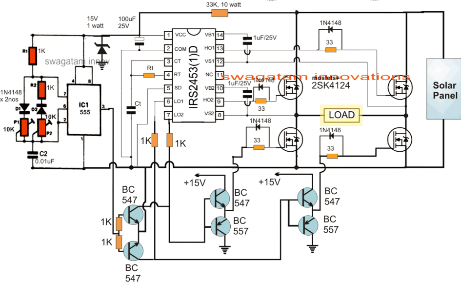
The IC IRS2453 enables the making of an efficient full bridge inverter circuit extremely easy. As can be seen the output of the IC just needs 4 N channel mosfets to be integrated for implementing a full bridge inverter actions.
The IC has a built-in oscillator, so no external oscillator stage is required for initiating the shown IRS2453 IC circuit. The Rt, Ct network associated with the IC determines the operating frequency of the inverter, and is supposed to be set at 50Hz or 60Hz depending on whether the operating voltage of the air conditioner is 220V or 120V respectively.
The IC 555 shown the left of the design is employed for generating a sine wave equivalent PWM feed for the full bridge inverter output.
The controlled PWM from the IC 555 is fed to the gates of the low side mosfets via the buffer transistor stage made through the BC547/BC557 pairs.
The above PWM feed helps the load to operate with an optimized RMS and alternating current which can be expected to be a close equivalent of the sinusoidal mains AC waveform.
The two pots associated with the IC 555 needs to be correctly adjusted until the required RMS and waveform is determined for the air conditioner.
Solar Panel Specifications
The 300V from the solar panel can be seen connected with the high side mosfet drains, which is stepped down to 15V through the indicated 33K, and 15V zener diode for providing a safe Vcc operating voltage for the two ICs.
Once the above procedures are implemented and appropriately set, the proposed 1.5 ton air conditioner can be effectively run throughout the day using only solar panels, without the need of any grid or utility power inputs.



Questions & Answers
Thanks Mr Swagatam with the 1.5ton solar air con inverter circuit. Can the same circuit be used for a 1.5hp /230vac submersible pump and what subtractions can be made to make it simpler. Or what changes can be made to run it on 100watt 12vdc panel:Rated V=17.82v: Rated I=5.62a: Open circuit V=21.6v: Short circuit V=5.35a
Please assist
Regards,
Zvap.
Hi ZVAP, thanks!
yes it's possible but the panel rating will need to be above 3000 watts, otherwise it won't work
How it should regulate?….please elaborate with detailed specifications
Thanks Mr Swagatam with the 1.5ton solar air con inverter circuit. Can the same circuit be used for a 1.5hp /230vac submersible pump and what subtractions can be made to make it simpler. Or what changes can be made to run it on 300watt 36vdc panels: Please Help
Regards,
Zvap.
Thanks Zvap, yes this design can be used for a pump which may be equivalently rated…in fact this inverter circuit can be effectively used for all higher power load applications.
you can either put the 36V panel in series to create a DC 330V and operate the circuit directly, or use a 36V to 20V transformer across the points "LOAD" to convert the 36V into a sinewave 220V.
hy,,,
i tried your lot of projects,,,,
but i am worried in this project..because this ic2453 is not aviable near me..
please tell me any replace or other ic…instead of this2453
Hi Thanks, there's no replacement for IC2453, you can search online for "full bridge driver IC"….hopefully you may find other alternatives.
Hi Swagatam , i am busy ordering components , what is the value for Rt and Ct in the circuit , and also am struggling to find 2sk4124 Mosfet , lastly you mentioned an option of using a 36V to 20V transformer across the points "LOAD" to convert the 36V into a sinewave 220V !! Can you explain more on this point
Hi Lufono, Rt, Ct will need to be solved either through experimentation or by the formula which may be found in the datasheet of the IC.
if your panel voltage is not 350V then you might require a step down transformer rated at 220V and the other winding rated at the solar panel level.
for 36V panel the primary will need to be 24V…so the trafo could be 24V/220V…and current for the 24V side could be calculated by dividing the required wattage by 24V
this 24V side will need to be connected across the indicated "load" points
Hi Swagatam , I managed to order all components in the circuit except the 2sk4124 but got the IRFP460 it have the similar rating to 2sk4124 , is it advisable to use?
IRFP460 would be fine if the panel is 350V… for a 36V panel you might require IRF540 instead….
hi sir,if iwant to use this circuit for higer wattage ie 4000 watts with 4 pnaels of 30 volt each 30v*4=120 volt and 3 strings in parralel to make higher current.what kind of changes do i need to do in this circuit.thanks
Hi Ravipal. no changes would be required except the mosfets which will need to be rated at 150V @ the specified current…
Hello Swagatam
Just this one question, I have got 0.37 KW Submersible Pump AC 220V Single Phase .
Thinking of using the above circuit
The Pump rated current is 0.37KW
Pump Input Voltage 220 VAC Single Phase
I plan to use the above circuit with a 36V Panel 720 Watt
Will it be sufficient to run as long as there is sun
Thanks in advance
Hello Lufono, yes it will be enough to run it almost as long as sun is present.
you will need a 0-24V/330V transformer connected across the "load" points of the inverter circuit for generating the required 220V from the 36V input.
Thanks again, just to be sure of the trafo , does it have to be 0-24V/330V to generate 220V?
330V is the peak voltage, 220V is the RMS….to make it simple you can use any standard step-down transformer rated at 24V/5amp/220V
Respected Swagatam hope you will be fine and doing great i am here to know what the 15v is all about where it goes thank you
MShah, it's for providing a 15V regulated DC supply to the ICs
Swagatam, thanks. But this circuit will produce Square wave not smooth sine wave, this may lead to rise in compressor temperature then to burn. right?
Alothman, you can replace the 555 PWM section with a PWM circuit, as presented in the following pages to get a smooth sinewave outcome…
https://www.homemade-circuits.com/2017/04/arduino-spwm-generator-circuit.html
https://www.homemade-circuits.com/2016/08/sg3525-pure-sinewave-inverter-circuit.html
Hlo Swagatam sir,
Hope you are doing well . Please help me i have two queries first one is where is MJE13005 and please mention the wattage of different resistors attached with BC 547 and 555 . for 50HZ what is the appropriate value of Rt and Ct.
Thnx and Regards:
Krishna Kaushik
Hi Krishna,
I am sorry, MJE is a printing mistake there’s no such part in the design so please ignore it.
all resistors are 1/4 watt rated except the 33K resistor
Rt Ct will need to be calculated using the formula expressed in the following article:
https://www.homemade-circuits.com/5kva-transformerless-inverter-circuit/
Hlo Sir,
Any designer available here in your contacts , who Can make this “Solar Inverter Circuit for 1.5 Ton AC ” for us. please send me a quotation at kmkaushik21@gmail.com
Hello Krishna,
I can build it for you but I will test it with a small battery and a small load. As you will know that the same circuit could be tested with the specified 1.5 ton load at your end, since the mosfets will be responsible for handling the load, not the circuit.
Sir we need complete prototype with smooth sine wave from PWM circuit and ready to attach with AC and solar modules of rated wattage. And plz send me best quote for this at kmkaushik21@gmail.com
Krishna, that can be difficult, because to satisfy perfect conditions I may have to experiment a lot and spend many days with it, which could make the project too costly for you, and finally we may have differences with the result performance and that could further cause complications, so I am sorry this project will not be possible for me…
Sir atleast tell me the price so that i can talk further for this .
Krishna, actually it is not just about the cost, the main issue is lack of time. It will be difficult for me to spend more than one day for any project, since I have to attend my website work also, and this project can take much longer time, therefore I am sorry it won’t be possible…
Sir I make this circuit proper working.in the morning and evening when no sufficient light output fluctuate .So any circuit handle this situation
Yogesh, I am glad it is serving the purpose for you…however for insufficient solar light voltage fluctuations will be present, nothing can be done in the circuit to rectify this issue.
One remedy that seems feasible is to add a lead acid battery in parallel with the solar panel, such that during bright sunshine the battery is simultaneously charged by the panel, and during insufficient sunshine, the battery compensates the situation by supplying its own power to the AC.
Yogesh,
This circuit is not for newcomers, it is strictly for the experts, a schematic representation can be a lot different than an actual set up, therefore you must have a complete knowledge regarding how mosfets needs to be set up with an IC….. and there are many other crucial things that needs to be considered.
An electronic circuit as complex as this must be tested stage wise and never together, I hope you know this.
The full bridge section is taken from the datasheet of the IC so do you mean the datasheet is wrong?
And how can the IC burn, when Vcc is 12V? The IC can only burn when the IC inputs come in contact with high voltage, or if there’s other fault in your connections or componenets
If you think the circuit is wrong then you must specify the fault in the design otherwise it is better that you get some thorough knowledge of electronics and only then comment.
Or get some experts help in analyzing your design.
Take the help of an expert, it is not recommended for the newcomers…or please tell me what is not correct in the design
Have you understood how the stages are designed to work?? If you have understood then you must be able to troubleshoot the actual fault
Dear Swag,
I think 2SK4124 is not available in India. What other MOSFET can be used in its place?
Dear Nirmal, you can search online for 500V 10 amp mosfet or other combinations such 400V 10amp/20amp mosfet etc
Thank you dear Swag.
you are welcome Nirmal
Hi Mr Swagatam , I am busy prototyping on the circuit , stage wise, For the 0.37 KW Pump I mentioned earlier , just having few question , I am not so good in calculating RT/CT in the circuit , can you suggest the CT /RT value if using 36V 620 watt Power Solar as Input , and 24v/300V Step Down Trafo between Points Load .
Secondly , I require your advise on this two options for the circuit. apllication
1.Transformer Based , the one I mentioned above
2. Transformer less
Thinking of buck boosting the 36V to 310 VDC as you have advised on one of the 555 Buck Boost discussion and fed the 310VDC to the circuit .
I do not know which one is better in terms of efficiency though the second option is cheaper to build .
I will appreciate your input
Rasaka, I appreciate your efforts, thank you!
Rt/Ct can be set with some trial and error, initially you can try any random value such as a 33K resistor and a 0.1uF capacitor…and check the output frequency with a frequency meter, and then gradually tweak their values either individually or together and in this way you can reach the desired frequency range.
This frequency range will depend on your country specifications….either 50Hz or 60 Hz.
A transformer based will be a better choice because it will work in a flyback mode and cause less heating on the mosfets, whereas a boost topology would load the mosfets heavily on each cycle and cause more heating on these devices.
Thanks a Million , I will update on the development
Hi Mr Mswagatam , I am working on the circuit , just one challenge , the bootstrap capacitor does it have to be polirised or non-polirised , i mean 1uf /25v
how to test the gates if the IC is oscilating with LED on this one
Hi Rashaka, it can be polarized, the upper lead will be positive, and the lower negative….the value will need to be experimented a bit, upto 10uF can be to tried to check which one gives the most optimal response.
Sir… what is value of Ct and Rt
Thanks
The formula can be found here:
https://www.homemade-circuits.com/simplest-full-bridge-inverter-circuit/
hello sir.
i’ve designed an inverter. it’s output is 220v but it doesn’t support bulb of 40w. and the transfo that i’ve used is powerfull.
what can be the problem my sir!
Hello Paul, Please specify the ratings of the transformer and the battery, I’ll try to help!
HIE SWAG,
Thank you very much for such a wonderful circuit. How do you then incoorparate batteries and the charging system for the batteries. Am saying so because the airconditioning system should also work during the night.
Thank you Bernard, you can add an appropriately battery bank with the solar panel, so that it charges during the day, and could be switched to the inverter mode during night.
Hie Swag,
About connecting batteries, are there supposed to be some changes or modifications to the circuit since the output that powers the 1.5 tonne air conditioner is ac. I am a bit confused here.