In this post I will show how to construct a circuit which will notify the user via SMS if the water supply to you area / home is initiated. It can show the time when the water is begin to supply and ended, average water flow speed in liter per minute and total water delivered to your tank in liters.
Introduction
We all know that life on earth is impossible without water, as human beings we use more water than any other species on earth consumes, not only for our survival but also to meet our luxury needs.
We not only consume water but also contaminate water bodies. The water consumption and demand is going to skyrocket in coming decades.
As a world citizen, it is our duty to save water, but as an individual we may not satisfy the entire world’s thirst by saving water but, we can definitely satisfy our family’s thirst as we might have healthy amount of water for brief period of time, even if no one around us saved water for future.
The supply of water in India and other rapidly developing countries is limited and also on high demand, moreover the water supply can begin without any official notification from the local government. This project will solve this issue for us.
Now let’s dive into the technical details of the project.
The Circuit:
The circuit consists of a water flow sensor YF-S201, an Arduino board which is the brain of the project, a GSM module (SIM 800 or SIM 900) for receiving SMS alerts on water supply and a real time clock module for tracking the correct time for water supply initiation and termination of water supply.
9 Volt supply is desirable for powering the Arduino board and the GSM module, it is recommended to provide the power supply from 9V adapters or homemade well-built, transformer based (LM 7809) supply.
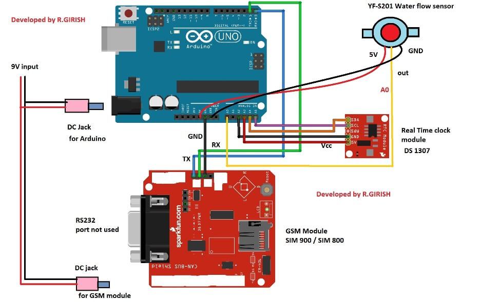
The connection between Arduino and GSM module as follows:
Arduino TX to RX GSM module
Arduino RX to TX GSM module
Arduino GND to GND GSM module
Never try to power the GSM module from Arduino’s 5V output pin to 5V input of GSM module.
The RTC or real time clock module will track the time of arrival of water and termination of water supply.
That concludes the hardware.
To set the time on RTC we need to upload time setting program to RTC with the completed hardware setup. This will sync the time on your computer to RTC.
Download the RTC library file: github.com/PaulStoffregen/DS1307RTC
RTC TIME-SETTING PROGRAM
#include <Wire.h>
#include <TimeLib.h>
#include <DS1307RTC.h>

int P = A3;
int N = A2;

const char *monthName[12] = {
"Jan","Feb","Mar","Apr","May","Jun",
"Jul","Aug","Sep","Oct","Nov","Dec"
};

tmElements_t tm;

void setup() {

  Serial.begin(9600);
  while (!Serial);

  // Power the RTC module
  pinMode(P, OUTPUT);
  pinMode(N, OUTPUT);
  digitalWrite(P, HIGH);
  digitalWrite(N, LOW);
  delay(200);

  bool parse = false;
  bool config = false;

  if (getDate(__DATE__) && getTime(__TIME__)) {
    parse = true;

    // Write time to DS1307
    if (RTC.write(tm)) config = true;
  }

  if (parse && config) {
    Serial.print("DS1307 configured: ");
    Serial.print(__TIME__);
    Serial.print(" / ");
    Serial.println(__DATE__);
  }
  else if (parse) {
    Serial.println("DS1307 Communication Error");
  }
  else {
    Serial.println("Could not parse compiler time");
  }
}

void loop() {
}

bool getTime(const char *str)
{
  int Hour, Min, Sec;

  if (sscanf(str, "%d:%d:%d", &Hour, &Min, &Sec) != 3) return false;

  tm.Hour = Hour;
  tm.Minute = Min;
  tm.Second = Sec;

  return true;
}

bool getDate(const char *str)
{
  char Month[12];
  int Day, Year;
  uint8_t monthIndex;

  if (sscanf(str, "%s %d %d", Month, &Day, &Year) != 3) return false;

  for (monthIndex = 0; monthIndex < 12; monthIndex++) {
    if (strcmp(Month, monthName[monthIndex]) == 0) break;
  }

  if (monthIndex >= 12) return false;

  tm.Day = Day;
  tm.Month = monthIndex + 1;
  tm.Year = CalendarYrToTm(Year);

  return true;
}
This above code reliably sets DS1307 without communication errors.
MAIN SMS WATER SUPPLY PROGRAM
Replace +91xxxxxxxxxx with your real mobile number.
#include <Wire.h>
#include <TimeLib.h>
#include <DS1307RTC.h>

int X, Y;
int sec = 50;
int t = 0;
int i = 0;

int check = 1;
int chk = 0;

int P = A3;
int N = A2;

int tim = 0;

float Time = 0;
float frequency = 0;
float waterFlow = 0;
float total = 0;
float LS = 0;
float average = 0;

const int input = A0;
const int test = 9;

void setup()
{
  Serial.begin(9600);

  pinMode(input, INPUT);
  pinMode(test, OUTPUT);
  analogWrite(test, 100);

  // Power RTC
  pinMode(P, OUTPUT);
  pinMode(N, OUTPUT);
  digitalWrite(P, HIGH);
  digitalWrite(N, LOW);

  // Startup delay
  for (i = 0; i < sec; i++) delay(1000);

  // GSM Setup
  Serial.println("AT+CNMI=2,2,0,0,0");
  delay(1000);
  Serial.println("AT+CMGF=1");
  delay(1000);

  Serial.println("AT+CMGS=\"+91xxxxxxxxxx\"");
  delay(1000);
  Serial.println("Your water supply notification system is ready.");
  delay(200);
  Serial.println((char)26);
  delay(2000);
}

void loop()
{
  tmElements_t tm;

  if (RTC.read(tm))
  {
    // Time conversion
    if (tm.Hour > 12) tim = tm.Hour - 12;
    else tim = tm.Hour;

    // Water Flow Measurement
    X = pulseIn(input, HIGH);
    Y = pulseIn(input, LOW);
    Time = X + Y;

    if (Time == 0)
    {
      // No water flowing
      if (chk == 1)
      {
        sendSMS_End(tm);
        resetFlow();
      }
    }
    else
    {
      // Water is flowing
      frequency = 1000000 / Time;
      waterFlow = frequency / 7.5;
      LS = waterFlow / 60;

      if (check == 1)
      {
        sendSMS_Start(tm);
        check = 0;
        chk = 1;
      }

      t = t + 1;
      total = total + LS;
      average = (total / t) * 60;
    }
  }

  delay(1000);
}

void sendSMS_Start(tmElements_t tm)
{
  Serial.println("AT+CNMI=2,2,0,0,0");
  delay(800);
  Serial.println("AT+CMGF=1");
  delay(800);

  Serial.println("AT+CMGS=\"+91xxxxxxxxxx\"");
  delay(800);

  Serial.print("Time: ");
  Serial.print(tim);
  Serial.print(":");
  Serial.print(tm.Minute);

  if (tm.Hour >= 12) Serial.println(" PM");
  else Serial.println(" AM");

  Serial.println("The water is being supplied now.");
  delay(200);
  Serial.println((char)26);
  delay(2000);
}

void sendSMS_End(tmElements_t tm)
{
  Serial.println("AT+CMGF=1");
  delay(800);
  Serial.println("AT+CMGS=\"+91xxxxxxxxxx\"");
  delay(800);

  Serial.print("Time: ");
  Serial.print(tim);
  Serial.print(":");
  Serial.print(tm.Minute);

  if (tm.Hour >= 12) Serial.println(" PM");
  else Serial.println(" AM");

  Serial.println("Water Supply is Ended.");
  delay(200);

  Serial.print("Average Water Flow (Litre/Min): ");
  Serial.println(average);
  delay(200);

  Serial.print("Total Water Delivered: ");
  Serial.print(total);
  Serial.println(" Litre");
  delay(200);

  Serial.println((char)26);
  delay(3000);
}

void resetFlow()
{
  t = 0;
  total = 0;
  average = 0;
  chk = 0;
  check = 1;
}
Full Working Explanation
Setting Time On The RTC Module
Now I will let you understand how we will set the internal time inside the DS1307RTC module and we do this in a very slow, step by step manner so you understand everything.
So we are using RTC time setting program and we upload it first before we touch our main SMS program, because then if you upload in wrong order then nothing will work.
Now we connect the RTC module exactly as per circuit diagram and we also connect P to A3 and N to A2 so the RTC module gets its power from the Arduino board itself.
Next you open the Arduino IDE and you copy paste the RTC time setting program. Then when you compile and upload the program, the Arduino automatically takes the compiler date and compiler time from your computer system and it puts this value inside tm.Hour, tm.Minute, tm.Second, tm.Day, tm.Month, tm.Year and then it writes this data inside DS1307.
Now when you open the Serial Monitor then you see a message that the DS1307 is configured and you see the time and date printed.
So we understand that the time has been successfully loaded inside the RTC. Now let us wait a moment and let the RTC stabilize for a second. So now the RTC is ready for using with the main program.
Next you can disconnect and reconnect Arduino power and the RTC module will keep the time because of its internal battery. Now the time setting task is complete. After this we go to the main program where we check water supply and send SMS notices.
Main Water Supply Notification Program
In this part we take the main program, and we upload it only after we have successfully uploaded the RTC setting program. Now we tell you step by step how the program works in very simple English.
Now when the main program starts, we do Serial.begin, we start GSM module, and we send the first message that your water supply notification system is ready.
This message is only for confirmation that everything is working. Then we read the RTC time through RTC.read(tm).
Then if the RTC gives the correct time, then we move ahead to measure the water flow using pulseIn on pin A0.
Now then if the sensor pulses show some value, then we calculate Time = X + Y, and then we get frequency = 1000000 / Time, and then we get waterFlow = frequency / 7.5, and then we get LS = waterFlow / 60.
So now this tells us how much water is flowing right now.
If the flow starts for the first time, then the program sends an SMS saying that water supply has started.
Then we initialize t, total and average. Then we keep adding LS every second and we keep updating average = (total / t) * 60. So we get minute wise average reading that is meaningful for the user.
Now when the pipe becomes empty because water stops flowing, then pulseIn gives us Time = 0, so the program understands that now the water supply has ended.
Then we send another SMS telling that water supply has ended. Then we also send the Average Water Flow and the Total Water Delivered in litres.
Now this helps the user to understand how much water came during the supply period.
Now once the SMS is sent then we reset all values to zero so that next cycle of water flow is recorded fresh and clean.
So this whole loop keeps repeating every second, and the RTC provides the exact time stamp for every SMS.
So the user always knows the correct starting and ending time of water supply.
Now the program keeps running continuously without any need of manual reset and it will work daily whenever water arrives because the RTC always keeps the correct time.
So this system helps the user to get instant alerts and water consumption data even when the user is not present at home.
Here is the tested prototype’s SMS screen shot:
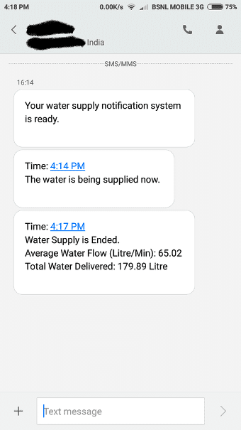
· After a minute powering the circuit ON, you will get an SMS saying that the system is ready.
· When the water starts flowing through the sensor, the system will notify the user with time.
· After the water supply is terminated the system will send another alert and summarize the session with time, average water flow and total water delivered to your tank.
Author’s prototype:
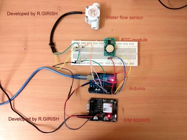
Please note that at the time of water arrival the water must free flow, meaning if there is any block or tap which is closed will not notify you.
If you have any questions regarding this project, feel free to express in the comment section, you may receive a quick reply.


Comments
I am confused by the GSM module. Can it simply send an SMS just like that? Doesn’t it require a SIM-card to connect to the net?
Thanks,
J
Yes a SIM will be required, that’s why we have to enter the SIM number in the Arduino code.
Connections please
Iam currently working on a project title DTMF based load control system where the load is synchronous motor of water supply. The circuit have gsm sim800l,arduino uno R3,single channel relay , whenever I’ll make a call to the gsm module it will turn ON/OFF the motor accordiingly with respect to command given from the mobile keypad after that,I want the flowsensor/flowmeter feedback to my mobile via sms, saying whether the flowmeter is started working the not (ON/OFF)like flowmeter is ON like that. flowmeter is connected to motor. PLEASE HELP ME WITH THE CODE
Unfortunately my coding skills are not good, so I may not be able to solve your problem….the above article was written by an external author.
will this send the time ended even if it has 1hr or more duration?
I am a beginner, How do I upload the RTC and Main Program in the Arduino
Actually I am also not good with Arduino,, so I cannot help you with this issue…this article was purchased from another author.
is it possible to save the data to sql database? how?
can i use breadboard instead of 9v dc jack for gsm module? TIA
If you are comfortable with the connections then you can use it.
sir why cnt we plug the sms power to arduino 5v power output?
1st program should be uploaded to arduino connected with RTC or only to RTC individually
Hi rahul,
The RTC with Arduino.
Regards
Mr.GR will reply you soon…
Dear Swagatam Ji,
Dipawali ki bhut bhut shubhkamnayen.
Happy Dipawali.
Regards,
Devendar
Thank you Devendar Ji, wish you too a Very Happy Dupawali!!