A electronic combination lock is a device which is designed to activate an electrical solenoid locking system whenever the correct combination of numbers are entered into an attached keypad.
To build this type of electronic combination lock, normally an electronic circuit with a keypad is used.
In the design I have explained in this article, however, no complex electronic circuits or ICs or keypads are used, rather the system uses a few mechanical rotary switches, and a cheap solenoid, and that's all is needed to build this cheap yet very effective simplest combination lock circuit.
Simple Combination Lock
The basic structure exhibited in most combination locks is based on the simple design as shown in the following figure.
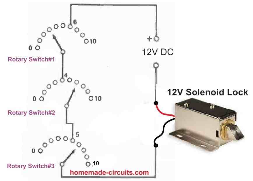
This requires just three ten-way rotary switches arranged in such a manner that if the right combination is entered on them, they will connect electricity to the relay or solenoid (the code being 6-4-5 in this case).
This simple circuit is rarely used in reality since adjusting the switches through all 1,000 potential combinations (0-0-0 to 9-9-9 inclusive) in a rational manner takes just a few seconds.
Combination Lock with Delay
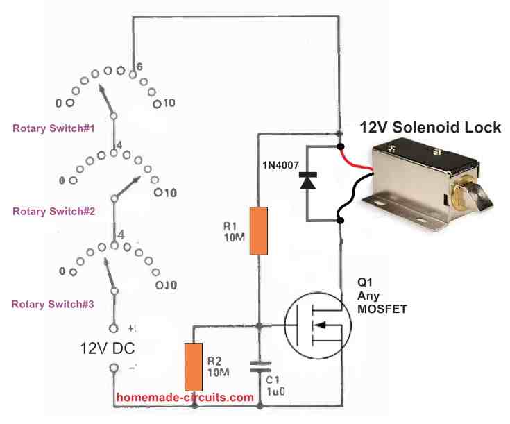
One of the simplest and most effective solutions is to incorporate a delay circuit into the device as shown in the following figure, which prevents power from being delivered to the solenoid or relay until the proper combination has been engaged for a few seconds.
Working through all of the available combinations hastily becomes ineffective at "cracking" the system because the delay circuit prevents the device from reacting even when the proper combination is held for a short instant.
Whoever attempting to "hack" the device is unlikely to succeed unless they are aware of the delay circuit and are willing to spend a significant amount of time figuring out the proper combination.
A time delay circuit dependent on FET semiconductor Q1 is included in the following circuit. C1 will be discharged when the right combination of SW1 to SW3 is adjusted and power is applied to the circuit, providing Q1 zero gate bias. As a result, Q1 is turned off, and no considerable current is sent to the relay or solenoid that serves as its drain load.
C1 charges gradually through R1, after around 4 seconds, the charge voltage on C1 is high enough to bias Q1 into conduction and turn on the relay or solenoid.
When the circuit is reset, R2 discharges C1, allowing it to immediately resume normal operation. The highest gate voltage of Q1 is limited by R2 to around half the supply voltage, however this is more than enough to bias the device hard into conduction and is of no practical significance.
D1 prevents probable harm to Q1 by suppressing the strong back EMF produced across the relay or solenoid when it goes off.
Solenoid
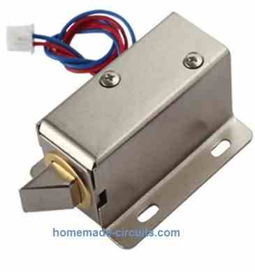
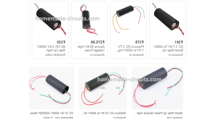
The solenoid can be any spring loaded type, with a shaft that would stretch outward in the absence of power supply, and pull inside as soon as power is supplied to it.
One popular type with matching specifications is shown in the following image.
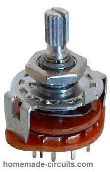
Rotary Switches
The 3 rotary switches shown in the above diagrams can be any ordinary 11 position rotary switch, such as the one shown in the image below:
Applications
The simple combination lock explained can be effectively used as a fail-proof security lock in various applications such as, table drawers, jewelry box, home doors, safe doors etc.
The code can be changed anytime simply by changing the wire positions across the 3 rotary switch contacts.
Simple Two Button Electronic Solenoid Lock Circuit
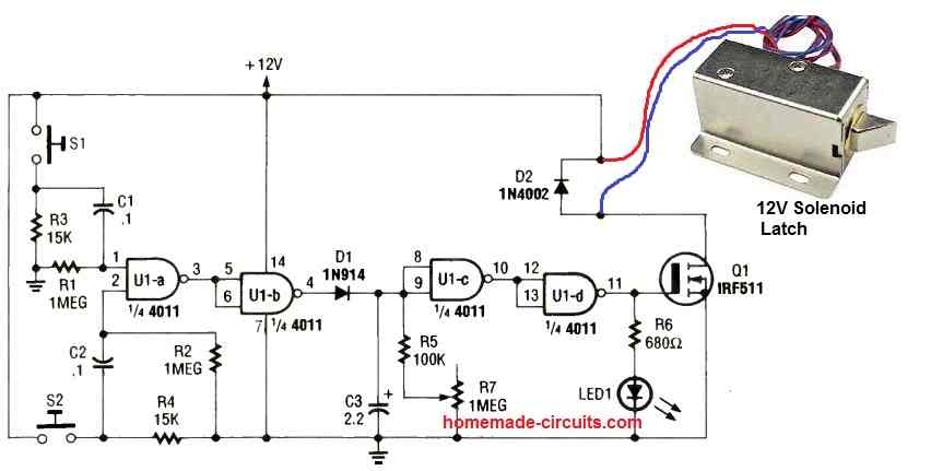
In this simple electronic solenoid lock circuit, the solenoid lock will unlock only when the S1 and S2 switches are pressed simultaneously.
Initially when power is switched ON, the situation will be like this:
Input of U1a being connected to ground, its output will be high. This will cause the U1b output to be low.
With U1b output low, U1c output will be high, which will cause U1d output to be low.
With U1d output low, the MOSFET will be turned OFF.
As long as the MOSFET is OFF the solenoid lock shaft will be projected outward, which will enable its locking feature. Thus anything which needs to be locked will remain locked in this situation.
Now, if S1 and S2 are pressed simultaneously, U1a inputs will go high together, causing its output to go low.
This will cause U1b output to go high, causing U1c output to go low. When U1c output goes low, it will cause U1d output to go high.
When U1d output goes high, it will activate the MOSFET and the solenoid latch. The solenoid latch shaft will withdraw inward causing the lock to open.
In this way the solenoid can be opened by simultaneously pressing S1 and S2 together.
C3 and R7 decides for how long the solenoid will remain in the open condition, until it restores to its original locking condition.

Comments
Thanks for the electronic lock. Please interested in a push button electronic lock wherein the combination lock can be changed whenever required. I am sure You must have designed this type of circuit, if yes please help me how to get to it.
Thanks
Regards
Ashok Sarin
Thank you Ashok, yes I have a few keypad based designs in this blog. You can check out the following link for more info on this:
https://www.homemade-circuits.com/?s=code+lock
It’s very good project.
Thanks
Thank you very much!
hello, wonderful circuit thank you very much. you are a source of inspiration for us
Thank you, it’s my pleasure!
Very nice simple useful project.
Keep posting such interesting simple electronic circuits.
Thank you and glad you liked the project!
Yes, a very simple and easy to build combination lock. But it does leave itself open to somebody leaving the combination open. So I prefer your previous circuit using push buttons switches.
Please don’t stop publishing your circuits, I have found many of the useful over the years.
Best regards
Yes you are absolutely correct. need a push button to open it by manually.if this project is using in room.
when the code is applied the lock will get powered and it will open and get unlocked. As long as the code is not applied, the solenoid will not receive any power and will remain locked.
Thanks for your interesting feedback, I agree with you!
Many many thank to serve the electronic world.
You are most welcome!