In this article I have explained a very simple 100 watt LED bulb circuit using a few high voltage capacitors. The entire circuit could be built at a cost less than $25.
I have already discussed many capacitive type of transformerless power supply circuits in this blog, however all these suffers from a couple of issues, namely lack of optimal current output, and surge inrush vulnerability.
Using Capacitive Power Supply
Upon studying capacitive power supplies deeply I could conclude a few crucial things regarding these configurations:
Capacitive power supplies are quite like solar panels which work efficiently, at their maximum power point specs when they are operated with their open circuit voltages, otherwise the current specs from these units go through heavy losses and produce highly inefficient results.
In simple words if we one desires to acquire high current outputs from a capacitive power supplies at will, the circuit will need to be operated with a load having a voltage requirement equal to the maximum output of the system.
For example with a 220V input, a capacitive power supply after rectification would produce an output of around 310V DC, so any load assigned with a 310V rating could be operated with full efficiency and at any required current level depending upon the requirement of the load.
If the above condition is satisfied, it also tackles the current inrush issue, since the load is specified at 310V, an inrush of full input voltage now has no effect on the load and the load remains safe even during sudden switch ON of the circuit.
Analyzing the The Design
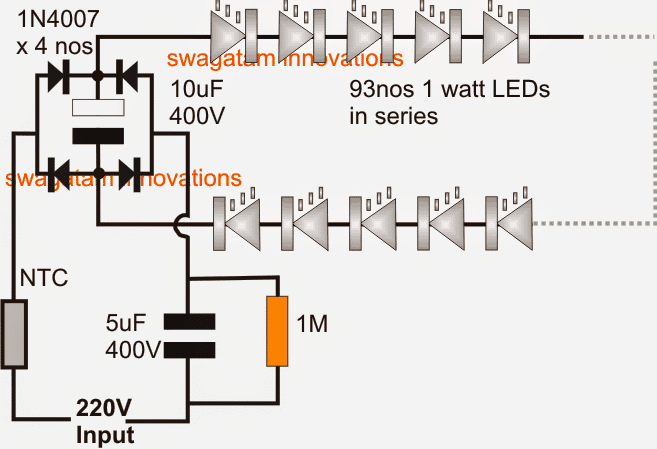
In the proposed 100 watt LED bulb circuit we employ the same technique as discussed in the above sections.
As discussed, if the input is 220V the load would need to be rated at 310V.
With 1 watt 350mA standard LEDs this would mean adding 310/3.3 = 93 LEDs in series, that's close to 100nos.
A single 1uF/400V capacitor produces around 60mA current at the above specified 310V DC, therefore for achieving the required 350mA more such capacitors will need to be added in parallel, to be precise a total of 350/60 = 5 capacitors, that could also be a single 5uF/400V but should be a non-polar type.
An NTC thermistor may be added for extra safety, although it may not be critically required.
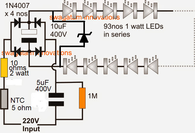
Similarly a resistor could be also included to provide extra bit of safety from fluctuating voltage conditions.
The resistance value may be approximately calculated as R = Us - VFd/I = 310-306/.35 = 10 ohm, 1 watt
For a 120V input, the above specs would simply need to be halved, that is use 47nos of LEDs instead of 93, and for the capacitor a 5uF/200V would be enough.
Circuit Diagram
Warning: Circuits I have explained below are not isolated from mains AC, and therefore are extremely dangerous to touch in the powered and open condition. You should be extremely careful while building and testing these circuits, and make sure to take the necessary safety precautions. The author cannot be held responsible for any mishap due to any negligence by the user.
The above diagram can be additionally safeguarded from surge inrush voltages, and mains fluctuations by adding a 10 ohm limiting resistors and a zener diode, as shown below.
Here the value of zener diode should be 310V, 2 watt
Improved design with current control
The following circuit is a foolproof circuit design that will never allow the LEDs to come across a stressful condition. The mosfet and thee associated current control ensure 100% constant voltage and constant current for the connect LED bulb chain.
The number of LEDs in the chain can be adjusted as per the selected voltage, or conversely the voltage can be adjusted as per the selected number of LEDs in the chain.
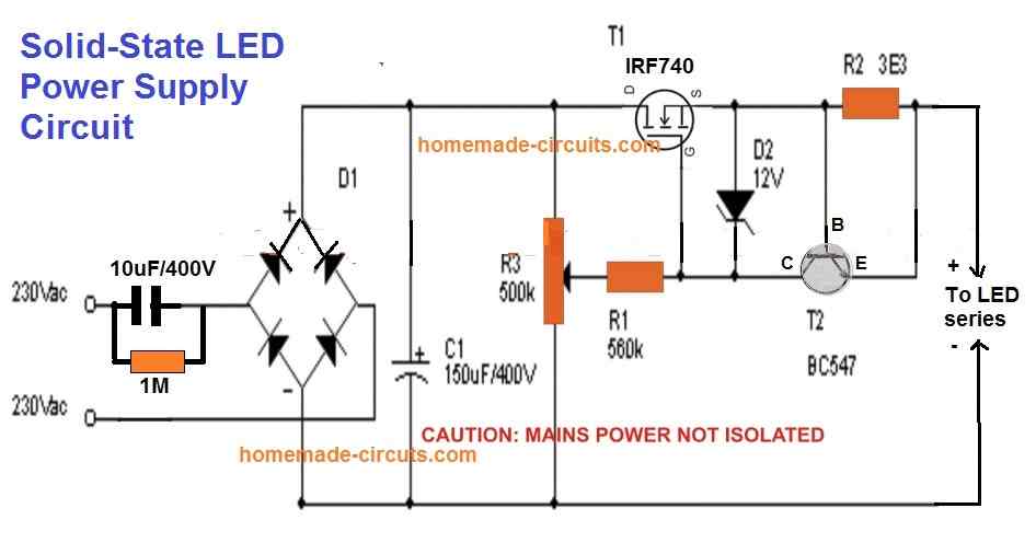
Note: Please move the capacitor C1 from the existing position to the output terminals of the circuit. Meaning, remove the C1 from across the bridge rectifier and connect it parallel to the LED string. This will drastically eliminate excess stress of the MOSFET, yet provide a filtered DC to the LEDs, increasing the overall efficiency of the design. In this case the voltage rating of C1 can be reduced to the value that's just slightly above the total forward voltage of the series LED string.


Questions & Answers
Please sir, Is it possible to get 4 ohms speaker from connecting 2 x 8 ohms speakers in parallel?[ie, R=(R1)(R2)/R1 + R2 ]. For instance, the IC, TDA7560 can produce 4 x 45w in 4 ohms speaker according to its datasheet. So does it mean that if i connect 2 x 8 ohms speakers in parallel, then connect it at the output of the IC, wil it produce the same 45w power as it would have done in a single 4 ohms speaker? Please help! ThanksPlease sir, Is it possible to get 4 ohms speaker from connecting 2 x 8 ohms speakers in parallel?[ie, R=(R1)(R2)/R1 + R2 ]. For instance, the IC, TDA7560 can produce 4 x 45w in 4 ohms speaker according to its datasheet. So does it mean that if i connect 2 x 8 ohms speakers in parallel, then connect it at the output of the IC, wil it produce the same 45w power as it would have done in a single 4 ohms speaker? Please help! Thanks
Yes it's possible to put two 8 ohm speakers in parallel for making a 4 ohm equivalent
Ok. Sir what is the minimum input voltage for the IC TDA7560? I could not find it in its datasheet
apply the input through a pot, as a volume control
Sir i am having a challenge on this: i have an Mp3 with Ic 4863 that is dual channel( two outputs with speakers, rated 3w, 4 ohms) i want to remove the speakers and replace it with any of the input pins of the Ic TDA7560(so that the TDA7560 can amplify it further). But my problem is that the output pins from the Mp3 that went to the 3w, 4 ohms speakers has none that is connected to ground(GND), but the inputs of TDA7560 is ground compatible(ie, its inputs are connected with respect to ground; GND). My question is how can i do this because if i should go ahead and connect it as required by the TDA7560 input schematic labelling it would amount to grounding two of Mp3's output pins wich i think will be harmfuld to its Ic(4863). Please direct me on what to do. Thanks!
Jideofor, just make the grounds of the TDA7560 and 4863 common, after this you can simply integrate the inputs of the TDA to any point that may be producing the audio in the MP3 system
Hello swagatam…. Its been a while now and that's because I av bin so busy dis year. Pls I need ur help again. I want 2build an LED circuitry that is efficient at consuming very low power of 60w for 11 rooms in a house. Which will b better, a JOULE THIEF or PWM circuit. Thankz
Hello tonisage,
a joule thief or a PWM both are efficient depending upon the dimensions of the intended input/put ranges.
these are efficient because they do not waste energy while operating, however the input power will be always equal to the output no matter which circuit is used.
If your application is at mains AC level, you can opt for a PWM driver circuit.
What if it is DC? Joule thief is more preferable?
for low DC applications and if control is not important, joule thief concept may be chosen
Ok sir. I measured the output voltage from the Ic 4863 that went to its speakers and it measured upto 8v(while music was playing), but when i measured the ouputs with respect to ground, it would produce at most 2v(while music was playing). And if i integrate a speaker to its output with respect to ground as you suggested, the music is usually low. My question is can i add an op-amp based preamp at its outputs to boost the outputs of the Ic 4863 from 2v to 8v so that the signal coming from its outputs with respect to ground would be the same as the one coming out of it without respect to ground? So that when i feed the 8v to the TDA7560's inputs, it will reach 51w. If it is possible, direct me on how to connect the following pins of the Lm324 to start functioning as the voltage amplifier(non-inverting inputs, inverting inputs and outputs) of all its stages because i want to make use of the whole 4 x op-amp stages inside the lm324 to feed the TDA7560 since its inputs is 4 in number and the outputs of the Ic 4863 with respect to ground is also 4 in number. Please direct me on how to calculate the feedback resistors too for defining the lm324's voltage gain, and finally the right supply voltage to use for the lm324
LM4863 is a powerful audio amp by itself and it's output should be more than enough for driving LM7560…no need of any external stages.
your construction may be incorrect somewhere, check it properly and as I suggested earlier you should use the recommended PCB for making the amplifier for eliminating any chances of faults and doubts..
Sir you are getting it all wrong. I said the Ic 4863's outputs are not ground compatible, and getting the outputs with respect to ground will make the ic to produce 2v instead of 8v, because its speakers are not connected with respect to ground (the outputs of the Ic 4863 is just like the output of TDA7560, non of them came from GND) and it is producing more than enough power to drive the TDA7560(without connection to ground. But from ground, the output will reduce. Just guide me on how to configure the op amp lm324 as preamp
Jideofor, single-ended amplifiers will also respond to its output directly. It's important to confirm first whether your amp is alright or not.
I do not have any idea how to make a LM324 driver stage for it.
sir ui make the circuit of fm bugger circuit from electronichub site .i sed the values of 47.8uH and 50pF of tank circuit but no result at proteous .canu guide mu?????
chaand, send the diagram to my email ID I'll check it
Hi! Sir, it's been a long time. Please sir,i have a question. I checked the datasheet of transistor 2N3055 and it said that Collector current(max)=15A, Collector-emitter voltage(max)=60V, Collector-base voltage(max)=100V and Emitter-base voltage(max)=7V. I want to use one of this transistor to design a class A amplifier circuit that can receive a power supply of 45V. But i want to design the voltage divider that can set its base reference voltage, and i want the output of the voltage divider to be around 35V. But my fear is that the 35V would be greater than the 7V emitter-base maximum voltage rating. Please how can i calculate the R1 and R2 that will form the voltage divider network to produce 35V from the 45V power supply without damaging the transistor? I tried it using a voltage divider that was producing 18V to the base of 2N3055 from a 20V power supply and it worked fine, but nw i want to increase the power supply to 45V and the voltage divider's output set to produce 35V but i want to confirm it is will be right and proberbly the right value to use for R1 and R2 for this result. Please sir, show me in full calculations on how you calculated their values. Thanks!
Hi Jideofor, Although I am not sure how and what you are trying to implement, because there are many class A amplifiers circuits online perfectly optimized and tested which you can simply copy.
7V is the emitter-base voltage, not base-emitter, so please do not confuse them with each other.
You'll need to take care about base-emiiter saturating voltage which is 1.5V for 2N3055
The formula for calculating the base resistor of any BJT is given in this article:
https://www.homemade-circuits.com/2012/01/how-to-make-relay-driver-stage-in.html
hello sir,
please suggest some initial and basic ideas for starting led tube lights and emergency lights production business regarding initial capital manpower space and other requirements as nobody other can not suggest better than you. what basic problems i can face while starting business and setting up it. your suggestions will be very appreciative and beneficial.
regards
sunny pawar
Hello Sunny,
I can only suggest suitable LED tube light and driver circuits, I have no idea regarding the business part of the subject.
Hello sir,
Its okay sir. Please suggest some efficient and reliable led drivers for tubes and bulbs for business purposes. It will be a great help for me.
Regards
Sunny
Hello Sunny,
Here are a couple of designs that you could try:
https://www.homemade-circuits.com/2014/02/simple-1-watt-to-12-watt-smps-led.html
The above is cheap, reliable but a mains non-isolated type.
The following are a little costly but fully isolated from mains:
https://www.homemade-circuits.com/2012/03/how-to-make-simple-12-v-1-amp-switch.html
https://www.homemade-circuits.com/2014/02/220v-smps-cell-phone-charger-circuit.html
Hello sir
I wish to create a rope light of 50 white leds with ac 220 supply. I want to replace all bulbs in the rope light with leds, as bulbs fuse now & then. Ive bought the leds. Please guide me with the circuit diagram with capacitor, resistors etc & how to go about. Please…
Hello Pritesh, you can use the same circuit which is shown in the above article, if the LEds are 5mm type then replace the 5uF capacitor with a 0.47uF/400V capacitor. that's all
connect all the LEDs in series and connect the ends as described in the above article.
Hello sir
I've created the rope light & is working fine. Thanks to you.
Now for 95 leds of specification 5mm 20mA 3.2v white what further modification would be required in yours circuit. Will the value of resistors, NTC, etc will also change?
Waiting for yours reply.
I forgot to mention the voltage in my previous message, which is 220volts . Thanks
Hello Pritesh, for 95 LEDs use 0.33uF/400V for the input capacitor, NTC may not be necessary, rest all can be kept as shown in the above diagram.
Please help with a very small but important project.
LED Latching Circuit using Transistor.
Power Supply: 3 or 6VDC
Load: 3 or 4 LEDs (I can calculate resistor sizes needed)
On Switch: Momenatry
Separate Off Switch, also Momentary
I'm looking for a SIMPLE transistor circuit that will turn on LEDs when Momentary ON Switch is depressed and STAY lit until the Momentary OFF Switch is depressed. This should be a simple ON/OFF circuit that latches in the ON condition until the OFF Switch interrupts the latched circuit. I have little knowledge in PNP. NPN, MOSFET devices, so I would very much appreciate it if you would select a small, inexpensive transistor for this circuit..
Yes it's possible but I am not sure about the accuracy of a transistorized circuit….just Google transistor flip flop circuit or transistor bistable circuit…you'll probably find many of these circuits.
However if you implement this using an IC, you would be able to achieve a highly efficient and a reliable design.
A transistorized design is shown below:
https://www.homemade-circuits.com/2014/03/transistor-bistable-flip-flop-circuits.html
and IC circuits can be witnessed below:
https://www.homemade-circuits.com/2011/12/build-these-simple-flip-flop-circuits.html
Do I need HEAT SINK for 93x1w LEDs ? Would the current be round 100mA or 350mA ?
yes you will need it, a large one, possibly with a cooling fan…the current would be 350mA
hi! i want to drive 25 pcs of 1w led usinf this ckt. just replacing 5uf with 3.3uf, removing ntc, adding 10uf 450v cap at the rectifier o/p and a zener diode of (25*3.3)=82.5v 1w for protection and a 500ma fuse at the i/p.. will it be a safe idea??pls reply
Hi, with 25 nos of LEDs the efficiency of the circuit will drop by a lot and the illumination will not be optimal. for ensuring optimal response the supply AC V spec must be close to the load V spec.
NTC is a must in any case and must be included, rest of the modifications are OK.
for heatsink i am using alluminium channel used for glass windows. i am clamping the 1 w led by fevikwik on the alluminium panels.. it should sink all the heat..
sticking with fewikwik is OK but not the recommended method, may just work, press it hard to reduce the film thickness between the LeD base and the aluminum.
Dear swagatam ! u told that 25, 1w leds would not give optimal illumination, but my concern is to replace my old tube light(28w) in my bed room. in that case 30 , 1w leds should give sufficient light in my bedroom only. your concern?? what glue should i use to stick leds on heatsink and how??
Dear Pritam,
for ensuring optimal response the supply AC V spec must be close to the load V spec.
25 x 3.3 = 82.5V, and the input is 220V so the difference is wide that's why you wouldn't get an optimal output….but adding 5 more LEDs may compensate the inefficiency.
You can use 40/50 LEDs with a 1uF/400V capacitor, this would provide nearly 25watts of light output without heating the 1 watt LEDs and you wouldn't need to put the aluminum strip.
Bro, i understand your explanations. I know that in case of transformerless designs it is preferred that the source voltage and load voltage be identical to avoid the surge issues etc.
but i wish to drive minimum number of leds with full brightness for ensuring my light efficiency and also the less cost. 50 leds will cost me a lot of money. waiting for your suggestions.
Bro, in that case you will have to go for a SMPS unit, because with a capacitive PS and few LEDs you can never achieve the desired results
hello swagatam can u plz tel me how can we calculate zener volt and watt?
i m using 20 led, 40 led ,and 60 led in 3 diffrent circuit…..plz help me with zener value …
thanks
Hello manj, the zener volt should be a few volts above the total forward voltage of the LEDs and wattage twice that of the LED series wattage.
If we take the first example in your case, it would be as follows:
zener voltage = 20 x 3.3 = 66V so it should be 80V.
zener wattage = 2(wattage of the LED used)
example if 1 watt LEDs are used then the wattage of the zener would be
2(1) = 2 watt
….sorry the zener wattage will be = capacitor max current output x (supply V – LED fwd V)
if we assume the caapcitor current to be 500mA, then for the 20nos 1 watt LEDs it would be
0.5(310 – 66) = 122 watts
to avoid this huge value, the difference between the supply and the LeD fwd voltage should be as small as possible.
Thank you so much my friend.
hi Swagatam i m from Badlapur. This is not my comment but can u pls tell me where can i get this type of raw material for led circuits thanks
Hi Vijay, you will have to come to Lamington Road in Grant Road (Mumbai) for procuring the above parts or any related electronic part
…you can also try the online option for the same…
Bt sir how I can get 35v through 230v AC main for the LED
through an smps adapter
And how much amps led require
for 100 watt module, it would be 3amps