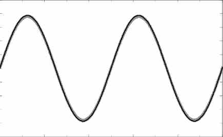
A sine wave generator is actually a sine wave oscillator circuit which generates an exponentially rising and falling sinusoidal waveform.
The 9 simple sine wave generator circuits presented in the following article are easy to build, since they incorporate a small number of ordinary electronic components, and can be used for generating an exponentially varying waveform with a specified frequency.
The frequency is determined by an RC feedback network between the input and output of the circuits.
The kind of sine waveform that can be achieved from the following circuits can be witnessed in the following diagram:
1) High Quality Sine Wave Oscillator
The below indicated sine wave generator circuit is not only easy to build, it also provides an exceptionally pure output having a total noise and distortion level that is effectively under 0.1%.
The design is a simple Wien Bridge oscillator configured around an operational amplifier.
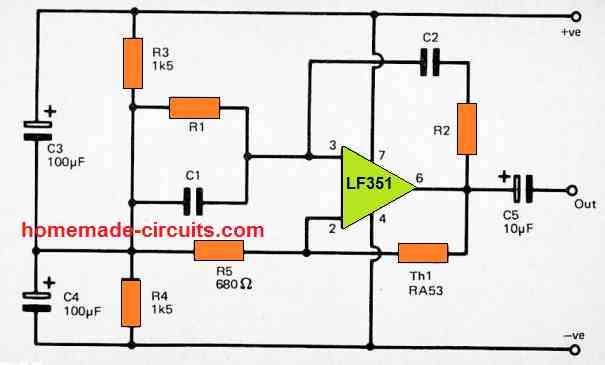
However, the circuit consists of thermistor Th1 used for stabilizing the closed loop gain of the circuit with a magnitude which can generate a very good quality output sine wave signal with an amplitude of around 2 volts peak to peak.
The one downside of this circuit is the presence of RA53 thermistor which has a useful property of self heating. This type of thermistor can be much costlier compared to the normal thermistors.
Nevertheless, the easy design of this sine wave generator and the an excellent sine wave output from this stabilization technique probably justifies the high cost.
Alternatively, you can replace the thermistor with a small 6 V incandescent bulb for getting the same effect
Capacitors C1, C2 and resistors R1, R2 are used for fixing the operating frequency of the output sine wave. Here, the resistor R1 value can be same as R2, and likewise C1 and C2 can also have the identical values.
The frequency of sine wave could be determined through the following formula
Frequency = 1/2πCR
This implies that, if the operating frequency is approximately 1 kHz, then C1 and C2 could be around 4n7, and R1 and R2 could be set at 33k. Modifying either the resistors or the capacitors allows an oppositely proportional variation in the frequency value.
It is recommended to have the values of the two resistors between a few kilohms and many Megohms. For the capacitors any value in the range of a few pFs or higher can be just fine.
Having said that, you cannot use polarized type of capacitors like electrolytic or tantalum elements, and practically speaking this condition restricts the value of the capacitor to around 2.2uF maximum.
It is possible to make the output frequency of the sine wave adjustable by replacing the R1 and R2 with fixed resistors and by putting a potentiometer in series, and it is certainly essential to utilize a twin gang potentiometer to ensure that R1 and R2 series values could be altered in a combined way.
The circuit works with a least supply voltage of around 6 volts, and the the circuit can tolerate a absolute maximum 36 volts.
This simple sine wave generator circuit can be efficiently driven through a dual balanced power supply using the center tapped 0V supply being generated by the resistors R3, and R4.
If the circuit is powered through genuine dual supplies, then obviously, R3 + R4 tend to be unnecessary and could be eliminated.
2) Simplified Sine wave Generator
The next figure below shows the circuit design of another sine wave generator that is essentially exactly like the previous design.
However it works with a technique of gain stabilization which does not depend on an expensive thermistor.
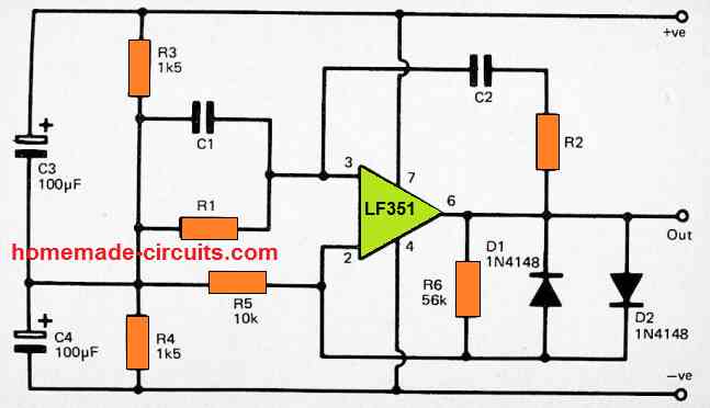
Diodes D1 and D2 are employed to minimize the closed loop gain of the amplifier as soon as the output voltage becomes higher than around +/-0.5 volts, which effectively prevents the circuit from going into a erratic oscillating mode.
This in turn avoids the possibility of high clipping and distortion on the output signal.
However, you may find a substantial level of distortion on the output sine wave output signal, which may not be acceptable for applications in which high quality sine wave is expected. The output level of the sine wave signal is around 500mV RMS.
3) Using Audio Amplifier LM380
The circuit is built around an audio power amplifier device (IC1) utilized in a phase shift oscillator circuit.
A three-section phase shift circuit is used to provide feedback between the output and the inverting (−) input of IC1. R2 - C1, R3 - C2, and R4 - C3 constitute the three parts, each of which provides 60 degrees of phase shift at a specific frequency.
As a result, at this frequency, the three parts have a total phase shift of 180 degrees. With the provided settings, the circuit oscillates at roughly 1k5 Hz.
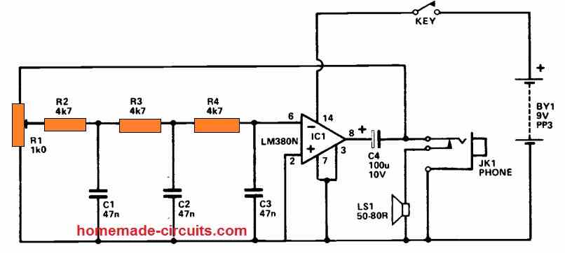
A circuit of this nature should typically generate a sinewave output since a clean audio tone is pleasant to listen to for extended periods of time.
Here, this sine tone replicates the waveform generated by a real CW (Morse) communication when it is processed by a receiver.
If the gain of the amplifier just marginally compensates more for inefficiencies in the feed-back circuit, this circuit will produce a relatively pure sinewave.
This is accomplished by changing R1 to provide the desired loss level via the feed-back channel. Due to the absence of feedback, it is backed off near the point where oscillation ends.
C4 and a break connection on the output jack socket provide the output signal to the speakers. If a plug is pushed into the output socket, it immediately turns off the speaker.
The unit has an output power of around 100 mW rms and a current usage of roughly 20mA when the key is depressed.
4) Single Transistor Sine Wave Generator
A transistorized phase shift oscillator is a very easy to build circuit which can be used for generating a sine wave output signal.
Having said that, until some kind of gain stabilization is employed it may generate an output with extreme distortion levels.
The working frequency of this transistor sine wave generator is governed by 3 resistors and 3 capacitors.
Due to the involvement of 3 frequency regulating components it may not be possible to apply this design in applications requiring a variable or an adjustable frequency capability.
Another issue with this design is that it can be difficult to obtain gain stabilization satisfactorily.
For this reason it may be advisable to use this phase shift oscillator only in those circuits where a fixed frequency and an inferior quality sine wave signal are acceptable.
The complete circuit diagram for the simple transistorized phase shift oscillator can be seen in the above figure.
Transistor Tr1 is applied like a high gain common emitter amplifier having feedback configured across the BJT's collector/base pins by means of a 3 stage phase shift network.
The first stage is composed of capacitor C1 and R1, the second stage consists of C2 and R2, and the last stage is built using C3 and the TR1.
With a specific frequency we have a phase shift of 60 degrees via each of the stages of the phase shift network, providing an overall shift of 180 degrees.
Therefore, it is a design having a positive feedback and not a negative feedback which is generated across the amplifier, and the TR1 gain is adequately high to guarantee powerful oscillation around this frequency.
Theoretically the operating frequency can be calculated using the formula:-
Frequency = 1/2π6CR
This means that the gain of the amplifier is just adequate to sustain the oscillation, however when tetsed practically you may find it to be substantially higher than this.
Due to this the actual frequency of oscillation is quite low compared to the calculated number, and the operating frequency is actually usually no more than 50 percent of the calculated value.
Therefore the part values indicated in the diagram provide an output frequency which is around 1 kHz rather than 2kHz.
The frequency of this simple sine wave generator circuit could be tweaked by altering the C1 and C3 values, and these values must be all identical.
Modifications in value provide an inversely proportionate shift in frequency.
The frequency of the circuit can be also adjusted by altering the values of the resistor, although it is best to keep R1 and R2 with a minimum value of 3k3, which must not exceed the 18k value.
Transistor TR1 could be just about any high gain NPN Silicon transistor for example a BC109C or BC108C or a BC547.
5) Another One Transistor Sine wave Oscillator
A basic phase shift oscillator may be built using a single transistor.
The output is a sinewave with something like a 'lump,' indicating that the distortion percentage is somewhat significant, around 10%.
This isn't always an issue; when creating audio tones, a large harmonic content produces a much more intriguing sound. By inserting a potentiometer (25 ohms) into Q1's emitter lead, the sine wave perfection may be improved.
When the resistance is set such that the circuit is only slightly oscillating, the sinewave becomes reasonably clean.
But, if the power supply voltage changes, the oscillation may stop completely. The working frequency may be changed by connecting a 10k potentiometer to R3 or by altering C1, 2, 3. Putting C1, 2, 3 equal to 100nF reduces the operating frequency in half.
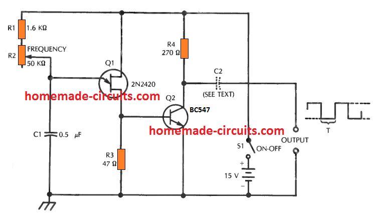
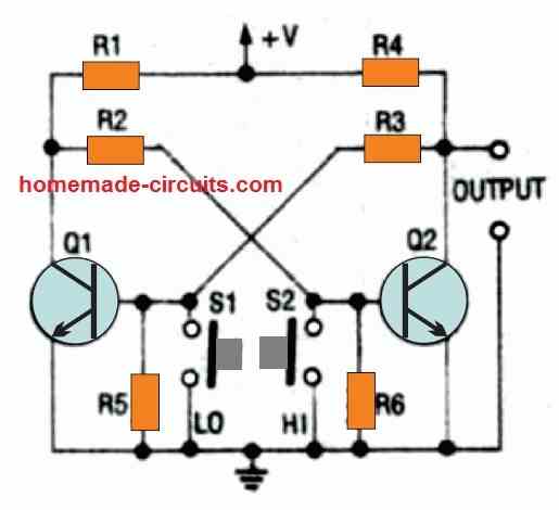
6) Using Two Transistors
When complete, this circuit will generate a sinusoidal waveform with a peak-to-peak voltage of around 8 volts and a frequency of roughly 500 Hz.
This reliable test tone may be used to track sounds via a sound system or to simply annoy the nearby residents.
Changes to the RC networks: what would happen? Does this change the tone? I leave this up to you to investigate.
7) Variable Sine Wave Generator Circuit
The circuit presented here generates a high-quality sinewave output across three continuously variable ranges (Range 1, lower than 20Hz to over 200Hz; Range 2, lower than 200Hz to over 2kHz; and Range 3, lower than 2kHz to over 20kHz), which span more than the full audio frequency spectrum.
The Wien Bridge type circuit is used, which comprises of an amplifier with frequency selective positive feedback given by a C-R network. This network's capacitive elements can be whatever is switched by the two capacitors SW1.
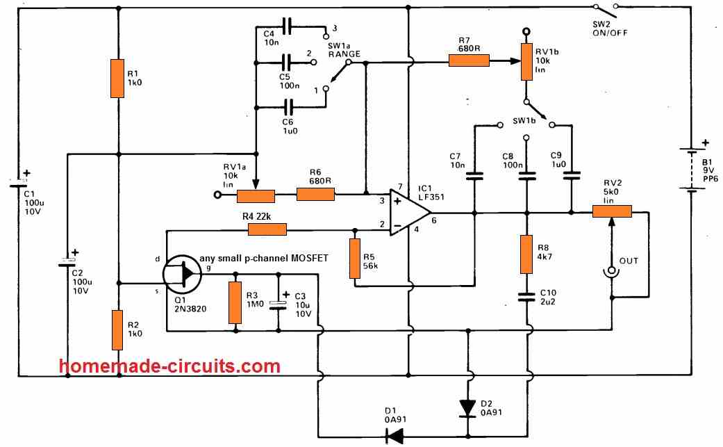
R6, R7, and RV1 are the resistive components, with the latter allowing the sine wave output to be adjusted throughout the above mentioned ranges.
This network offers positive feedback over the FET-based operational amplifier IC1, which has low noise and distortion.
The non-inverting input of IC1 is likewise biased by RV1a and R6 to a central tapping on the supply generated by R1, R2, and C2. If satisfactory waveforms are to be achieved, the closed loop gain of IC1 should be kept at exactly the right amount.
To ensure steady operating parameters and a consistent sine output level, an automated gain control (AGC) circuit is utilized.
A negative feedback network is formed by R5, R4, and Q1's drain to source resistance, that regulates the closed loop gain of IC1.
Q1 is first forward biassed through R3 in order to provide adequate gain for powerful oscillation.
R8 and C10 link a little of IC1's output to a rectifier and smoothing network made up of D1, D2, and C3. This results in a positive bias, which attempts to turn off Q1, resulting in lower circuit gain.
The higher the bias and the smaller the gain, the harder the circuit oscillates. The output may be varied from zero to roughly 1V5 rms using the adjustable attenuator RV2.
The circuit's current usage is around 7 milliamperes.
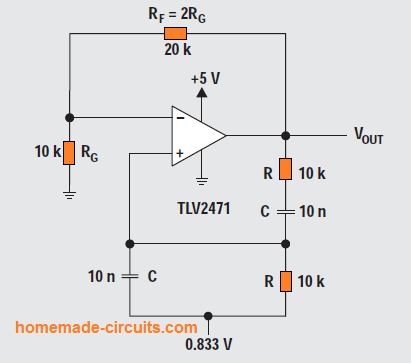
8) IC 741 Wien Bridge Sine wave Oscillator Circuit
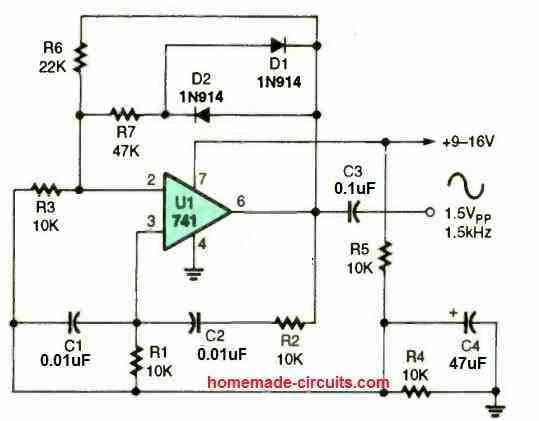
The operating frequency of the circuit is determined by C1, C2, R1, and R2, where a 741 opamp is wired up in a Wien-bridge, audio sinewave oscillator setup.
The oscillator's frequency is stabilized by utilizing metal film resistors and NPO capacitors. This setup is stable enough to be used with tone-control applications.
By replacing R1 and R2 with a dual-gang linear potentiometer, it is simple to transform the fixed-frequency oscillator depicted into an adjustable oscillator.
Various paired values for C1 and C2 can be used to span alternative frequency ranges. Lower frequencies are produced by bigger values, while the opposite is true for smaller values.
Another 741 IC Sine Wave Oscillator Circuit
This uncomplicated sinewave oscillator finds applicability across a broad spectrum of scenarios demanding a stable sine wave at a specific frequency, while maintaining low distortion.
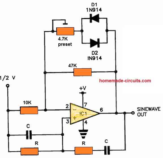
Most operational amplifiers (op-amps), such as the 741 or 301, can be effectively employed in this setup.
The selection of values for resistors (R) and capacitors (C) can be determined through the use of a mathematical formula.
The 5k trimpot allows for precise adjustment of the output level.
The midpoint at 1/2 V can either be derived from a well-bypassed resistive divider connected to the power supply rail or through the use of a supply rail splitter circuit.
To calculate the output frequency, the following formula is applicable: 1 / (2πRC), where the capacitance (C) is measured in Farads, and the resistance (R) is expressed in Ohms.
9) Hi-Fi Sine wave Generator Circuit
Here is a small circuit assembly capable of providing a Hi-Fi sinusoidal radio-frequency signal with very good stability and a very low distortion rate. It is cost-effective and very easy to build.
All hobbyist need, at one time or another, a small sinusoidal oscillator to adjust a circuit, a Hi-Fi chorus, or modulate an HF signal?
This assembly is intended for those who haven't yet invested in purchasing a "sinusoidal generator" that delivers a low distortion voltage.
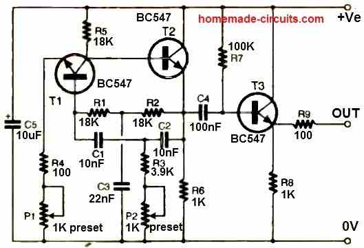
Circuit Description
The setup consists of three stages with NPN transistors. High-gain amplification is achieved by T1, which is configured as a common emitter. Its collector is directly connected to the base of T2 (common collector).
The selective double-T filter is positioned between the emitter of T2 (resistance R6) and the base of T1, i.e., between two points with opposite phase.
Stage T3 lowers the impedance and prevents load variations from disturbing the oscillator's characteristics.
The biasing for the base of T1 is obtained from the emitter of T2 through the resistors R1 and R2 of the filter, simplifying the circuit.
The filter consists of resistors R1, R2, R3, the adjustable P2, and capacitors C1, C2, and C3.
Ideally, the conditions P2 + R3 = R1/2 = R2/2 and C3 = 2C1 = 2C2 should be satisfied to ensure perfect filter symmetry and optimize the oscillator's operation.
However, achieving this configuration with standardized component values to generate a specific frequency, such as 1000 Hz, is challenging.
Thus, the R3 + P2 branch is varied while maintaining R1 = R2 and C1 = C2, with C3 close to 2C1. This allows frequency adjustment within a restricted range of 10 to 15%.
Different frequencies can be obtained by modifying the values of C1, C2, and C3.
The resistor R4 in series with the potentiometer P1 serves as the emitter load of T1, and the gain of the stage is adjusted using P1.
The dynamic impedance of T1's base is high as the emitter is not decoupled, which optimizes the filter's operation.
The useful signal is taken from the emitter of T2 at the terminals of R6. It is sent through C4 to the base of the output transistor T3, configured as a common collector.
The biasing of this transistor is ensured by resistor R7. The output signal is available at the terminals of R8, at the emitter of T3.
It is sent to the output terminal through a protection resistor R9. The output impedance is approximately 150 ohms.
The power supply voltage, decoupled by C5, can vary within wide limits without significantly altering the oscillation frequency defined by the filter characteristics.
This allows obtaining a nearly distortion-free sinusoidal signal with a power supply voltage ranging from 3 to 30 V.
Naturally, for each intermediate voltage value, the signal's amplitude varies, and the gain adjustment needs to be adapted.
Sine Wave Generator using a Single UJT
By including a parallel tuned circuit in series with base 2 you can get a sinusoidal output from the UJT oscillator, as indicated in the following figure.
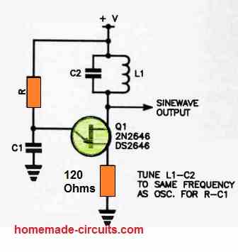
This involves aligning the relaxation frequency of the UJT with the frequency of the tuned circuit.
When the emitter fires at base 2 and produces current pulses these pulses causes the L-C tuned circuit to resonate, which results in rather impressive sinusoidal output
Comments
Hello Swagatam,
I have simulated some curcuits in Falstad and noted that wave voltage is always above 0.
Is it possible to create circuit using only discrete elements that produces sin waves between +1V and -1V (like in home socket)?
Thank you.
Thanks Leon,
That may be possible if we use a dual supply for the circuits…meaning now all the zero volt or the ground referenced symbols in the diagram are connected to the (-) of the dual supply, while the output is measured with reference to the center ground supply line of the dual power supply….
Sorry, my comment regarding looking at circuit #6, needs correction:
“shouldn’t C3 10uF be drawn the same value as C4 i.e. 0.1uF?”
(my typo lol)
You are absolutely right, both C3, C4 must have identical values – 0.1uF. Thank you very much for mentioning it, I hope the other readers will find this information useful…
looking at circuit #6, shouldn’t C2 10uF be drawn the same value as C3 i.e. 0.1uF?
(Based on 60° phase shift per RC section, 10uF seems to be a typo).
Thanks for these circuit ideas.
Hi Swagatam,
Question about the second circuit in section 8 . I have a simple rail splitter circuit consisting of a resistor (100k) and a capacitor (10uF) divider in parallel across the positive and ground rails taking a virtual ground from the centre rail . I’ve sent you the circuit via email. How would I apply this correctly, including power supply to the op amp, to the circuit I mentioned?
Kind regards,
Alasdair
Hi Alasdair,
I saw the diagram, it should work as intended. You can consider reducing the resistor values to 10k, or use a 10k preset as shown below:
https://www.homemade-circuits.com/wp-content/uploads/2025/05/sine-wave-generator-using-wien-bridge-and-dual-supply.jpg
Is there a practical (and safe) way to rectify the sawtooth wave form from a generator to a pure sine wave? Obviously, the biggest hurdle being the big power requirements for the average home (120v and around 10kw).
If you are referring to AC voltages at 10kW then you might need to do it through an inverter, by converting the sawtooth into SPWM, through transformers.
There is a small issue with the 8th circuit, C2 and R2 are connected parallel on the schematic, but they should be in series. After this fix the circuit works well and the frequency is quite stable, i’m using it for a self-test board.
Thank you so much Zoltan, for the important correction.
I have modified the 8th diagram accordingly, please check it and let me know if it is alright or not.
Many thanks….
With this circuit can used to that is 50Hz as inverter oscilator
These circuits will not help to create a sine wave inverter.
I used circuit #4.
Change the bias resistor to 330k and T resistor to 5k6, that I have in my spare, give me ~1080Hz @400mVpp
It is sufficient for test purpose .
Thank you
Yes, 400mV should be enough for most test applications
Sir, i want to know if these sine wave oscillators can be used as an oscillator stage in an inverter to build a sine wave inverter circuit
Hi Alimon, sine wave cannot be applied directly to the gate or base of transistors for driving the transformer with sine wave, so it is not possible.
Hi I have bread boarded the Variable Sine Wave Generator Circuit and it works BUT that is to the scope when I try and connect to a audio amp it kills the signal Have tried a resistor / cap / elec non allow the siganl to come through the amp your comment
Hi, you can probably try using a transistor buffer stage in the middle and check if that helps. You can use a BC547 in emitter follower mode. Connect the base to the sine wave signal through a 100K resistor, connect the collector to a DC supply such as +5V or +12V, connect the emitter to the amplifier input.
I made your “Single Transistor Sine Wave Generator” variable by replacing R1+R2 with a double gang 10k pot wired in series with a 3.3k resistor on each side. Thank you!
Glad you could make it successfully!
What I can see is LF351 nothing else the rest is resistors and capacitors
Good evening swagatam
I can see in your write up about this circuit you mentioned thermistor but I can’t find one in it and why is’t so or is’t that you made a mistake in the circuit diagram?
Emmanuel, please see the first diagram carefully, the Th1 RA53 is the thermister