In this post I have explained how to build a simple crystal tester circuit using ordinary parts like transistors, resistors, diodes and capacitors.
What is a Crystal
A crystal can be used for making an electronic oscillator circuit by using the mechanical resonance of a piezoelectric vibrating crystal to generate an electrical frequency having a fixed, and a constant frequency.
This frequency can be typically employed to monitor time, such as in quartz watches.
Crystals are also popularly used for getting a constant, reliable clock signal for electronic ICs, and to ensure stable frequencies for radio transmitters and receivers.
The commonest form of piezoelectric resonator utilized is the quartz crystal.
Therefore, oscillator circuits depending on quartz for stabilizing the frequency, became popular as crystal oscillators.
However various other forms of piezoelectric components such as polycrystalline ceramics can be also found in related circuits.
A crystal oscillator begins oscillating due to the small alteration in its shape when it is subjected to an electric field, a characteristics known as electrostriction or inverse piezoelectricity.
When a crystal is subjected to an potential difference, it results in a change in its shape; and as soon as the potential is removed, the crystal produces a tiny voltage since it flexibly restores to its initial condition.
The quartz can oscillate with a constant resonant frequency, working in the same way an RLC circuit would, except with a much increased Q factor (minimal loss of energy during each cycle of the frequency).
After a quartz crystal is fine-tuned to a certain frequency (which can be dependent on the the mass of electrodes mounted on the crystal, the positioning of the crystal, ambient temperature and various other related factors), it successfully sustains this frequency with an enhanced stability.
Making a Crystal Tester Circuit
Crystals cannot be tested directly with a meter. There's no way these components can be verified using ordinary methods that is normally used for measuring parts like resistors, capacitors, or transistors.
However, the following simple crystal tester circuit works extremely well to detect if a connected crystal is faulty or working without any issues.
The above circuit will provide you with a direct indication whether the connected crystal is good or a bad one.
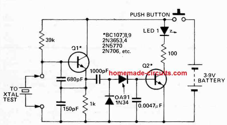
The configuration around the transistor Q1 and its associated RC network work like a Colpitt's oscillator. As soon the the crystal is hooked up into the indicated slots, the Q1 circuit starts oscillating at the crystal frequency.
This oscillating frequency is applied to the 1000 pF capacitor through which it reaches the two diode stage wired like a rectifier circuit.
The oscillating frequency is appropriately rectified using the diode network and fed to the next transistor Q2 stage.
The rectified DC from the diodes provide the necessary biasing to the Q2 transistor base, so that it turns ON illuminating the attached LED.
The switched ON LED confirms that the crystal under test is a good crystal, and the circuit is correctly oscillating with the help of the crystal.
If a bad crystal is inserted into the slot, the Q1 fails to oscillate which does not allow any frequency to enter the 1000 pF capacitor causing the Q2 stage to remain switched OFF.
The LED consequently also remains switched OFF, indicating that the connected crystal is a faulty one.
The Q1, Q2 can be any general purpose transistors such as the BC547.
Another Simple Crystal Tester Design
The crystal checker circuit shown below is designed to work with crystals that have a minimum fundamental frequency of 20 MHz.
Q1 is configured in the typical wideband Colpitts oscillator configuration. An output voltage doubler rectifier is used to convert the signal from its emitter and supply current to the base of Q2.
As a result, a functional crystal will generate oscillations, producing a rectified RF signal to activate Q2 and illuminate the LED.
While 4.5 V or 6 V batteries are also compatible, it is recommended to use a 9 V transistor radio battery as the power source for this circuit.
Simply press the button to observe the LED's illumination! To insert crystals into the appropriate crystal sockets for testing, you can make use of spring clips or binding posts.
These sockets can be connected in parallel to accommodate the crystals you wish to test.
Analyzing and Calculating the Parts Values
Oscillator Circuit (Q1 with Crystal):
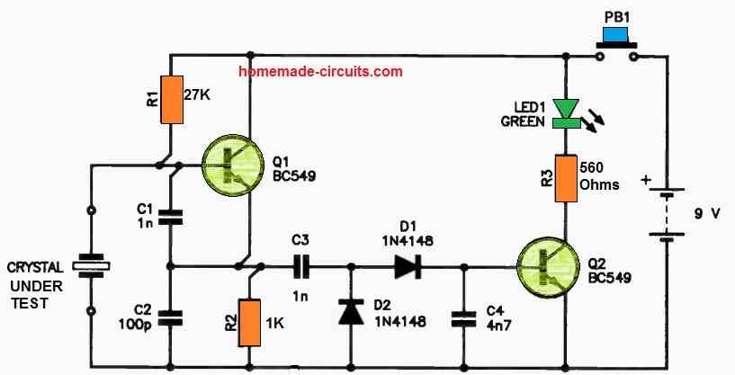
Resistor R1 (27 kΩ):
R1 provides biasing to Q1 (BC549) to ensure it operates in the active region and can oscillate.
Capacitors C1 (1 nF) and C2 (100 pF):
These capacitors form a feedback network in combination with the crystal to sustain oscillations. The values are chosen to match typical crystal capacitance requirements (e.g 20–30 pF for standard crystals).
Crystal Frequency:
The crystal frequency determines the oscillation frequency. For a valid crystal under test the circuit oscillates at the crystals resonant frequency. No oscillations indicate a defective crystal.
Coupling Capacitor (C3 = 1 nF):
C3 couples the oscillations from the collector of Q1 to the rectifier stage. It blocks DC while allowing AC oscillations to pass.
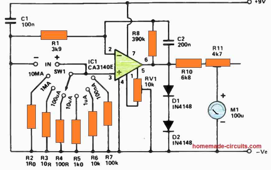
Rectifier Circuit (D1, D2, and C4):
D1 and D2 (1N4148):
These diodes form a full-wave rectifier to convert the AC signal into a pulsating DC signal.
Forward voltage drop per diode = 0.7V.
Peak voltage (Vpeak) after rectification = Vout (oscillator) - 2 * 0.7V.
Smoothing Capacitor (C4 = 4.7 nF):
C4 smooths the rectified signal into a steady DC voltage that drives the base of Q2.
Amplifier/LED Driver (Q2 and R3):
Q2 (BC549):
Q2 amplifies the rectified signal from the oscillator stage. A sufficient voltage at its base turns it on lighting up the LED.
Resistor R3 (560 Ω):
R3 limits the current through the LED (Green). Assuming the LED forward voltage is approximately 2V:
ILED = (Vsupply - VLED - VCE(sat)) / R3
Where:
- Vsupply = 9V
- VLED = 2V
- VCE(sat) for Q2 = 0.2V (approx.)
- ILED = (9 - 2 - 0.2) / 560 = 12.14 mA.
This current is within the safe operating range for the LED.
Crystal Tester using an UJT
Do you have any strange crystals in your repair drawer that you're not sure are okay or not? Use this easy good/bad crystal checker for validating your answers.
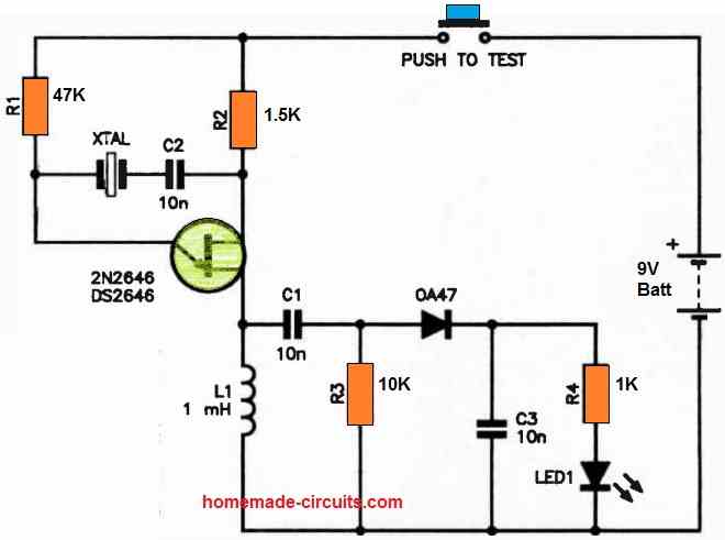
It is possible to use the 2N2646/DS2646 UJT as a feedback oscillator. If the crystal oscillates, the RF choke in its base 1 terminal generates an RF voltage across it.
The 0A47 germanium diode rectifies this voltage, which charges C3 and turns on the LED. It is advisable to choose a high luminescence LED due to the fact that it will light up using less than 1 mA of current.
A 9 V transistor radio battery is used to power the circuit.
To accommodate the varied crystal pin spacings, an array of compatible crystal sockets could be linked in parallel; pigtail leaded crystals could use spring terminals.
Simply hold down the button for a brief period of time to watch the LED light up. While it varies on the properties of each UJT, the circuit is compatible with crystals up to 7-8 MHz.
Additionally, overtone crystals with a fundamental spanning within this range will function. It works well for testing TV crystals, computer clock crystals, and other low frequency crystals.
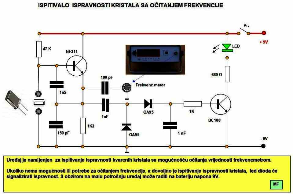
Crystal Tester using BF311
The below given crystal tester circuit was practically tested by M. Farkaš from Varaždin, Croatia, and generously contributed to this website. We sincerely appreciate his valuable contribution.

Comments
Thank you I made a bargan basement purchase (lesson learned).
after testing around 25 crystals I only found 2 that worked. I thought my circuit construction skills had gone south. Does this mean the 24, I have left are bad or is this some type of overtone harmonic trick 😃.
Yes, I think the 23 pieces that failed to operate are indeed bad…because if those crystals are not working on this basic circuit, chances are they won’t work anywhere else…
Hi Swagatam, I breadboarded your circuit and then perf boarded it permanent after I found out it does work. However, so many crystals were showing bad, I used a 100 MHz oscilloscope across the crystal to detect any vibration. After doing so, I had 3 piles of crystals, around 20 each pile.
The pile that lit up the LED at any brightness included 4-16 MHz markings, only a few were dimmer. The second pile which passed the oscilloscope test but not the LED at all were 12-50 MHz, only 2 or 3 were over 12 MHz. The third pile which did not pass either test were 24-32 MHz.
Therefore, I must conclude that the tester can determine that a crystal is good, but cannot differentiate when a crystal is bad, especially above 12 MHz. I also conclude this circuit is not tuned in such a way as to excite crystals over 16 MHz.
My question is whether this sounds correct to you, and whether there may be another variation of the circuit which can excite crystals at those higher frequencies. Maybe use lower value capacitors?
Thank you Paul for testing this circuit.
Yes, your findings look correct to me. Since you have tested the results practically it clearly shows that the circuit is not tuned to excite higher frequency crystals.
I think changing the capacitor values to lower values can make a difference, and the tester may be able to test higher frequency crystals also. This will need to be experimented by some trial and error.
Great! Will you be testing this, or is the new values something you can calculate and recommend? If it covers all crystal frequencies from 4-64 MHz then a new circuit is certainly worth the while. I was originally thinking my collection of take-off crystals was full of faulty parts until I realized only the higher frequency parts were rejected.
It would be nice if you could test it with some trial and error, because you already have the set up ready with you. You can try replacing the Q1 transistor with a BC547, and the capacitors with some lower values than the existing ones. Also I think the 39K resistor will also need to be varied to test if it affects the results.
I have built and hot melted the whole assembly, so I would rebuild a new circuit on a proto board. I don’t have any lower value ceramic disc capacitors to use, so maybe you could send some to me? That’s my limitation: all of what I have left are 1000 pf and above and have not found and low MLCC’s either. The transistors I am using are SS9014 max transition freq= 150 MHz. I did not have germanium diodes so I am using two Schottky SS14 high speed rectifier diodes. I’ve varied the input voltage between 5 and 9 volts with no difference. I selected the brightest LED at lowest voltage I could find too. Any reason the pushbutton is required? I think I would just use a USB input line at 5V and plug it in while using the circuit. There is insignificant current draw when an oscillator is not installed.
I have plenty of these capacitors with me and I wish I could send them to you. I think you can try putting capacitors in series to achieve the intended lower values.
The push button is given to prevent idle consumption of the battery.
Yes, a USB Dc supply is a good and easy way to power the circuit.
Great! I contacted you by FBM with my addy. Are both diodes OA91? Please clarify the marking of the schematic so I am sure. I understand how to calculate capacitors in series, thanks for the suggestion.
Yes both the ICs are OA91 or 1N34
Swagatam, we communicated on this crystal tester, and the other posted and this drawing is somewhat similar to the other with some minor component value differences. In the one I assembled even though you indicated there was a mistake and a transistor # indicated was a PNP, I assemble mine with both NPN as the drawing indicated. I didn’t use the part #’s given. Since the other drawing is indicating 1n4148’s and I am seeing very low base voltage, I’m wondering if the diodes are what is holding the oscillator down along with the 390R I am using at a 5v supply, perhaps this is not enough to turn on the LED indicator? I’m going to give this circuit a try and I’m also wondering if there is a circuit that uses an IC instead of 2 transistors. I will look online for one in the present time.
Yes, I think 1N4148 might not work correctly, so it must be replaced with germanium diodes such OA91 etc. A BJT circuit can be more efficient than an IC circuit according to me, since BJTs can work with voltages as low as 0.6V.
5V should be sufficient to turn ON any LED but only if the driver transistor conducts properly.
Sir your website is amazing. I realy liked it.I just wonder how the esaki oscilator circuits works.Can you explain the theory please ?
Thank you Ozan, I have one related circuit which you can read here:
https://www.homemade-circuits.com/how-to-make-single-transistor-led/