In this post I have explained a simple yet accurate programmable diesel generator timer circuit which can be used for achieving discretely programmable ON/OFF timing sequence for the connected diesel generator set. The idea was requested by Mr. Raj Kumar Mukherji.
Technical Specifications
Happy new year and hope you are fine. There is a request from one of my friend to design a variable programmable timer to run a diesel generator set.
It should work as follows based on the preset timings: a. The DG set will say start at 7am and stop at 10amb. It will again start at 2pm and stop at 5pmc.
It will start at 7pm and stop at 8.30pm There may be more such sampling that can be done on this based on the need.
Is it possible to design such timer keeping the cost within 2000/- and that the timer should run from 12 volts. Actually, there is a need for a low cost but accurate programmable timer which will be able to turn on and turn off a diesel generator set without manual intervention by the help of this timer.
The input which I got from my friend about the DG set is that it has a start switch and a stop switch.
Accordingly, there are 2 terminal sockets below each of the start and the stop switches to connect a programmable timer which will perform the on-off operations automatically.
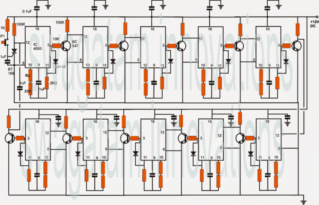
Therefore, we have to design the timer in such a way so that the start and stop signals drive a monostable multivibrator at the output of each of the ICs (IC1 to IC6, please refer to the attachment) to simulate the push button functions.
I would request your assistance on this with a special request to explain me how the cascading is done if we wish to include some more ON-OFF stages in the timer circuit.
It should be kind of momentary ON-OFF operation (on time for both motors/relays may be 5-10 secs each).
The process is similar to the manner in which the modern day bikes start (the start switch is PUSH type, contact is made when the switch remains pressed for about 5-10 secs and once the bike starts, the switch is released).
The Design
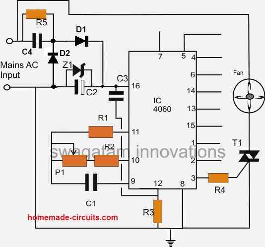
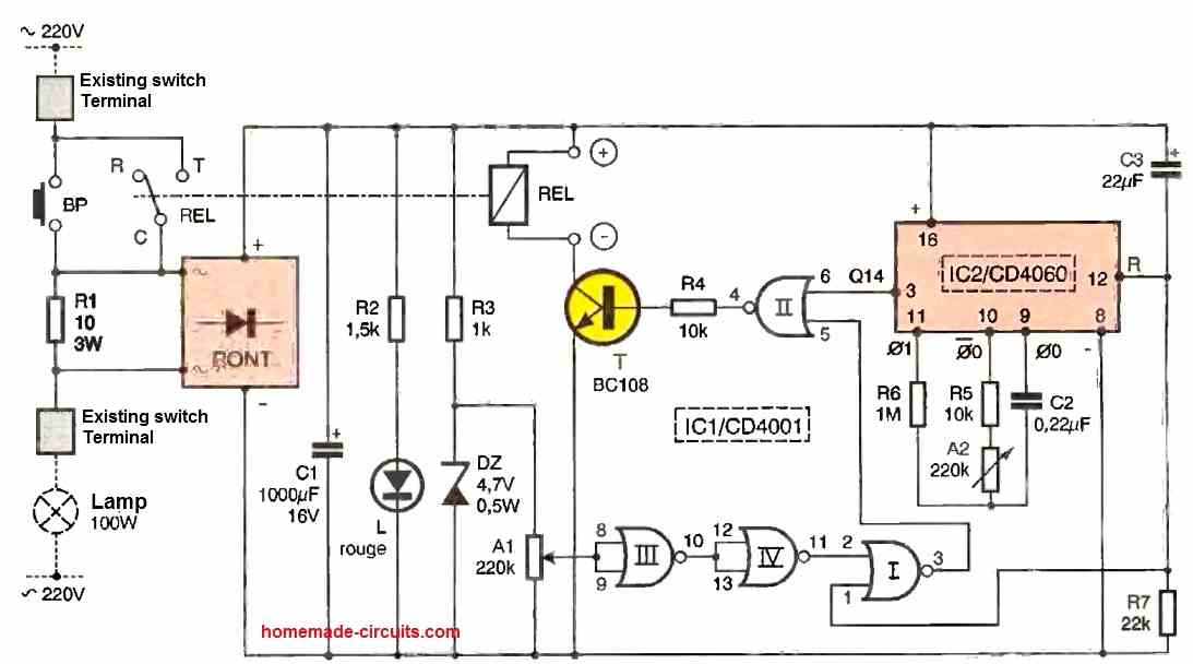
The proposed programmable diesel generator timer circuit was inspired from one of my previous circuits titled Automatic programmable school timer circuit, the entire explanation of the design may be understood therein itself.
The only difference being in the output triggering stage, here it incorporates a couple of relays triggered from the alternate 4060 stages, as I have explained below:
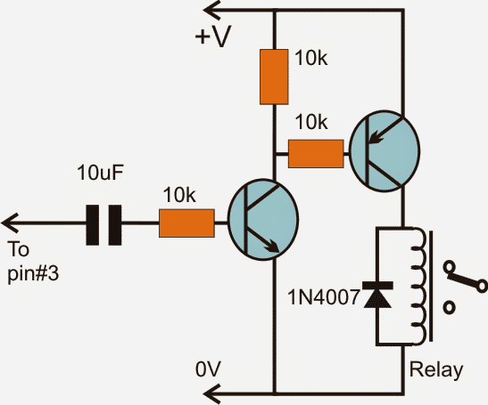
Relay Driver Circuit
The following circuit is designed for implementing the relay activation. This stage may be added to pin#3 of all the above 4060 timer stages.
The collectors of the PNP transistor of all alternate stages should be made common such that only two relays are involved for the alternate ON/OFF triggering.
For example if 10 numbers of 4060 IC stages are used, the transistor drivers associated with stage1,3,5,7,9 should have their PNP transistor collectors joined together for triggering the attached "start" relay, while the PNP collectors of stage2,4,6,8,10 could be joined together for triggering the attached "OFF" relay


Comments
Hello, do you consider triac as effective AC switch?
hi dear will u plese send me pcb desighning software that you use pllllllz dear i have demo version i want full version my email id. naumannaeem29@gmail.com regards
the full version is already explained above, you can read it and evaluate.
i use corelDraw software for the diagrams.