In this post I have explained a programmable bidirectional motor timer circuit for controlling a custom industrial mechanism. The idea was requested by Mr. Milton
Technical Specifications
I am a glass specialist, pretty good with DIY etc, but not too hot on electrics. I am planning a build for a 10mm Toughened Glass Watch display box, however our client would like this to be a watch winder box.
I have established that we require 4 x 10rpm 24V AC Motors to run simultaneously. They need to start turning every hour, for 15-20 minutes.
However, they need to turn clockwise then anti clockwise hour to hour. It would be good if I could also have a manual option to start and stop the motors when I wanted.
Is this something someone can help with? Please?
Thanks!
Milton
The Design
The proposed circuit can be understood with the following description:
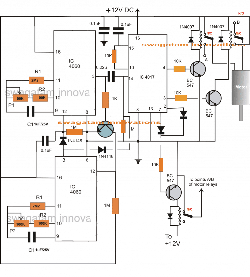
The stage comprising the two 4060 ICs are configured as a programmable stage. The upper 4060 IC is wired as the OFF timer circuit while the lower IC decides the ON time of the circuit.
The section at the right hand side consisting of the IC 4017 forms a standard flip flop circuit which toggles its output from 3 to 2 and vice versa in response to every high trigger at its pin#14.
When power is switched ON, The upper 4060 starts counting. This stage may be set for producing a time delay of 20 minutes as per the requested specs.
At the same time pin#3 of IC4017 produces a high logic since it's the start pin of the IC4017. The connected motor now starts spinning in a particular direction depending upon its polarity with the relays.
After the set 20 minutes, the time elapses, pin#3 of the upper 4060 becomes high which initiates the lower 4060.
This high from the 4060 applies a logic high trigger at pin14 of IC4017 via the 0.22uF capacitor which forces its output to hop from pin3 to pin2.
The relay at pin2/7 driver stage now activates cutting off the motor supply and thus halting the motor.
After about 1 hour which should be the specified interval set with the lower IC 4060, its pin#3 goes high and instantly resets the upper IC4060 so that it reverts to it previous mode.
In the process, it also toggles the IC4017 so that its output shifts from pin2 to pin4, the relay at pin4 gets restored and the motor starts rotating but now in the opposite direction.
The motor keeps rotating until the next 20 minutes after which as above the sequence of IC 4017 jumps to pin7 and the motor halts again.
With the later subsequent trigger from the lower 4060 IC, the system reverts to its initial situation and the cycle goes on repeating as proposed in the request.
Circuit Diagram

Comments
Hi, you may get some relevant information from the following page:
https://www.homemade-circuits.com/?s=3+phase+motor
Hi.
circuits for radio controlled model for aircraft devices and breakout and step motor driver circuits for CNC powerful.Please help me.
Presently I don’t have it, will try if possible…
hi SWAGATAM help me with wiring I want to replace DC motor with 12v ac two wire motor for above circuit .
hi Davis, An AC motor will not work with the above circuit, it has to be a DC motor only.
Sir I am an agriculturist in need a circuit to switch on a 300 watts motor for 5 minutes and off for 8 hours with repeating cycle. Sir kindly give me a perfect circuit for my needs and thanks in advance
Okay sir I accept your suggestion.
Rangathan, sure you can go ahead, 100K volume control pot will do…. but please remember that this project is not easy and can be completed only after proper understanding.
I would suggest you to build and test the following cirucit first, and then proceed with the rest
https://www.homemade-circuits.com/2012/04/how-to-make-simple-programmable-timer.html
Sir thank you very much for your kind reply and I am assembling this circuit. sir can I use 100 k volume control for p1 and p2 .
Ranganathan, you can effectively use the following circuit for your applications
https://www.homemade-circuits.com/2012/04/how-to-make-simple-programmable-timer.html
Good day sir,
After some interval(it helps me to recharge) I'm here to play with ckts through-out the hot summer (40-48 degree) of East U.P.
For your kind information, Google is doing everything wrong with the users of India(I think with all the countries of third world).
It optimises page…google find that you are on slow connection…huh.. 🙁
I think your blog post is quite famous and there is users all over the world, but your page appears after 3 to 5page,most useless sites of America (I guess) appears in first page…disgusting..
Now about the above ckt. I want to start a motor with switching on. After start it will run for 5-10 sec. in forward direction then it will stop for 5-8 min. then it will start rotate in opposite direction for 5-10 sec.then rest for 5-8 min then forward–rest–reverse–rest and so on untill it switched off. What kind of change I needed with the above ckt.
Egarly waiting for your kind advise.
Thanking you……
With regards..
K.kausik
Thanks Kikira, yes I too believe that my site deserves to be higher than the existing ranking.
the timing is the only factor which will need to be tweaked a bit as per your requirement specs in the above design.
the P1 pot for the upper 4060 and the lower 4060 will need to be appropriately adjusted for the required results.
So try the above circuit step wise so that you are able to succeed at the first attempt.
just make sure to add a 1N4148 diode across pin3 and pin11 of rthe upper 4060 IC…anode to pin3, cathode to pin11
Hi
I have built the circuit, I have the circuit running cw for the specified time then it stops for the specified time however it does not go to ccw, if left it completes the cycle and starts again going cw. I can't for the life of me work out what is going, do you have any test points or general points of reference I can refer to as part of my diagnosis?
Cheers ollie
…there should be a diode across pin#3 and pin#11 of the upper 4060IC, this will latch the upper timer IC once it has finished counting, if this diode is not placed then the upper IC will keep oscillating with its own delay periods, and interfere with the lower IC's counting and will mess the entire set up….I think I just forgot to put this diode in the diagram
you can check out the following diagram to see the how the diode needs to be placed.
https://www.homemade-circuits.com/2012/04/how-to-make-simple-programmable-timer.html
Hi, connect LEDs across pins2,3,4,7 and ground of IC 4017 to monitor the sequencing pattern…the sequence should move from pin3>2>4>7 and back to pin3 for the correct proposed operations of the motor.
also connect LEDs across pin3 and ground of both the 4060 ICs for monitoring the timing actions….all the LEDs must have their own 1k series limiting resistor