The PIR burglar alarm explained here will detect a human intruder within the stipulated range and sound an alarm. Thus, the system could be effectively use for detecting trespassing, theft, intrusion, burglars, or any form of unlawful entry inside a restricted area or zone.
Basic Principle
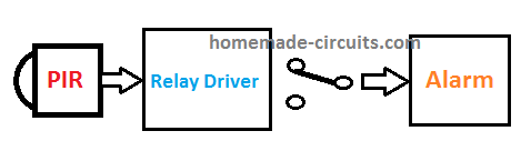
The operating principle of the proposed burglar alarm circuit can be understood by referring to the following block diagram.
The design looks very simple, since most of the complex infrared detection is carried out by the advanced PIR module itself.
The PIR module converts the IR radiation from human body into corresponding electrical signal.
These electrical signals are amplified by a single transistor amplifier which also works like a relay driver controller stage.
When a human intrusion from a burglar is detected, the PIR comverts the heat map of the intruders body into tiny electrical pulses.
The transistor receives these pulses and amplifies it sufficiently to drive a relay.
The relay switches ON, and sounds the connected alarm through its contacts.
How the Circuit Works
In the above paragraph I have explained about the basic block diagram and the working principle of the burglar alarm using a PIR sensor.
Now let's try to understand the precise details of the circuit configuration.
The design is based on a PIR motion sensor circuit which can be easily built using the following basic set up and applied as a burglar alarm circuit.

Here we can see, the system can be assembled using just 5 fundamental components, which are: 1) The PIR Module 2) A 1 k resistor, 3) An NPN transistor, 4) A Relay, 5) An Alarm Siren unit.
The PIR has 3 terminals labelled as the Vcc, OUT, and the GND or ground. The Vcc is supplied with a +12V via the 1k resistor, the GND with the 0V from a DC supply which could be from any standard 12 V AC to DC adapter.
Power Supply
Although the PIR is rated to work with a 3.3 V from a 5 V DC supply, for the sake of simplicity a 5 V regulator is avoided.
Instead a 1 k limiting resistor is used for dropping the 12 V supply to the required 3.3 V. The 3.3 V is achieved through a 3.3 V regulator which is provided inside the PIR module PCB.
Thus, the PIR works safely from a 12 V supply even without external voltage regulator circuitry.
The 1 K resistor also allows the circuit to eliminate the transistor base resistor, which further simplifies the shown PIR burglar alarm circuit concept.
The Relay Driver And Alarm Stage
The base of the relay driver transistor is directly attached with the OUT pin of the PIR for receiving the detected signal from the PIR module.
The transistor acts like a small signal amplifier as well as an effective relay driver stage.
Whenever the PIR detects a human presence which may be from an intrusion from a possible burglar or an attempt of theft, it converts the infrared heat map detection from the human body into corresponding 3.3V electrical pulses.
This DC pulse being higher than the 0.7 V switching bias for the transistor, the transistor instantly switches ON and activates the relay.
The relay contacts move from its initial N/C to N/O position which triggers ON the the connected alarm system.
Using an External Alarm
The burglar alarm system or the siren unit attached with the relay contact can be a homemade alarm circuit, or simply an external ready made siren, depending on the user preference.
Conclusion
The explained simple PIR burglar alarm circuit looks too simple to build yet provides an outstanding protection from all forms of human interventions, or intrusion inside a restricted zone, such as shops, homes, offices, lands, etc.
The system could be wired with a wireless transmission also for sending the detected intrusion to another destination such as police station or the owners residence.


Comments
salut
le transistor est en communication ou en amplification ?
Merci pour ton aide
Hi, the transistor is used only for amplification.
Mr. Swagatam,
First let me thank you for your help previously. I apologize for not knowing the right place to ask this question. I’ve searched your site but am unsure of the correct place to ask this.
Simply put: I am using a 12v RF fob remote relay to active an alarm system BUT I want a momentary “Chirp” of the alarm BOTH when I arm it AND Disarm it like a car does.
The more specific question:
I have a 12vdc alarm with an arming relay that has NO/COM/NC output which I can use to supply either (+) or (-) for the 1sec. 12v (+) pulse that will trigger another relay function (less than 1 amp) for lights and sound.
Any thoughts? Basically, want it to chirp when it is armed and disarmed like your car does.
Thanks again, I do appreciate all your help!!!
Respect,
Donald
Hello Donald,
you can probably try the following circuit for getting the chirping sound during arming/disarming of the alarm. You will have to connect another small relay with your mains relay, and use this new relay’s contacts to trigger a monostable. I am not sure if this the most efficient method, but I can’t figure out any other easy method of implementing this:
Mr. Swagatam
I breadboarded this a few times to make sure I did it right, but the alarm goes off continually as soon as I add power and the #2 trigger does not do anything when I attach it to 0V.
FYI, I am using a 12vdc power source
Any suggestions?
Thanks,
Donald
Hi Donald,
did you connect the relay contacts with pin#2 of the IC? If you did then yes, as soon as power is switched ON the circuit will sound the alarm for a moment and then the alarm will switch OFF. After this when the relay contact changeover the alarm will again activate for a moment. In this way the sound will activate for a moment each time the relay contacts changeover.
If you touch the pin2 manually then also the alarm should activate for a moment and shut off….if this is not happening then your IC 555 may be faulty or there may be some other issues.
This design is a very basic IC 555 monostable design and should work without issues.
Hi, thank you for this project and great explanation as always.
I have two questions if i may…..
How would i modify this circuit to re-purpose and old home alarm PIR. The ones with v+, v-, n/c+, n/c-, tamper+ and tamper- where the tamper and n/c is usually bridged with a resistor.
Also, when using one of those PIR’s from an old alarm, how will you make it “latch” with a reset button to “un-latch” and re-arm the system.
Thanks in advance for any assistance or advice.
Hi, for latching the relay, you can add the following modification across the N/O contact of the relay and the transistor base
…for adding a reset function, just add a push button switch across the base emitter of the transistor….while resetting the push-button the user must be away from the PIR detection zone..
Thank you very much!
Where would the second wire of the relay n/c connect?
You are welcome….N/C will remain open.
Thank you very much Swagatam. Really appreciate it!
Hello, I am selling solar security lights and trying to learn electronics basic, I want to know how do I calculate the size of resistor when I want to convert ( eg: 220V AC to 12V AC.) something like this means if we know input and output voltage how to calculate resistance size. I am sorry if you feel my question is not related to your topic.
Will be glad to here from you.
Thanks
Hi, if you convert 220 V to 12V through a resistor, the resistor will get extremely hot.
The formula is given below:
R = (220 V – 12V) / Load current
wattage of resistor = (220 V – 12V) x Load current
Hi Swagatam
Where can I purchase the Advanced PIR module? As in South Africa we can only buy the standard PIR, and I would like to build your PIR alarm system.
Thank you in anticipation
John van Heerden
You can get them at Comunica in South Africa in pretoria or Centurion
Hi John, In my schematic also I have used a standard PIR module. You can get this standard assembled PIR module (with fresnel lens mounted) from any online store like Amazon.
Hallo Swagatam
Thanks very much for your assistance and guidance.
John van Heerden
You are welcome John!
Keep up the good work sir
Hello Linda.
As Swagatam suggested you can hook this up without too much difficulty. Also, I built an alarm system for a 12′ x 24′ out-building using an Alarm system designed by Charles Platt. I included a timer module using 555 chips that gives me a delay to arm the system and leave the building. I adjust the timing circuit with a resister. The important part I wanted to share was I originally used a small 3″ 8ohm speaker which wouldn’t scare off a cat, so I simply soldered RCA wires to the 8ohm speaker and plugged it into a stereo amp with an outside 120w speaker. This is quite loud, so you may want to think about this. Simply cut one end off and separate the two wires; just don’t cut off the end that plugs into the amp (male end), then simply plug the male end into the amp, connect a speaker (typically mono) and you have a expensive loud speaker. Hope this helps some. Spencer.
Hi you are an inventor OK my problem is I have a big farm would like about buildings and animal shelters I need to build a system when the doors open and outdoor siren will go off I have tried smaller projects with magnets the door closing in an open and a closed Can you tell me a simple but operative alarm system not connecting to electric and or connected to electric preferably not electric maybe solar or battery Seems simple enough your wire siren to a close switch when the doors open it goes off where does the power come from I’m sorry I’m a woman and I’m not too technically advanced however I learn fast
They make the small rinky-dink magnetic door alarms but you can’t hear if you walk 5 feet away I need something that alerts me at my house or in the field that someone is entered stealing or harming my animals whatever can you help or point me in the right direction so appreciative
Hi, you can try the following concept:
https://www.homemade-circuits.com/door-open-close-alarm-circuit/
replace the 2N2222 with TIP122 transistor, and replace the alarm with a high power CAR siren. The power supply to the circuit can be from a lead acid battery 12V 7 Ah
Hi there, can this be made as a motion sensing car alarm,thanks
Yes, of course it can be used as a motion sensor car alarm.
Can I use a pcb mount solid state 4 pin relay to power this
Model KG3RD50D2-12
Regards
Brian.
Yes you can use it.