A phase-shift oscillator is an oscillator circuit designed to generate a sinewave output. It operates with a single active element such as a BJT or an op amp configured in an inverting amplifier mode.
The circuit arrangement creates a feedback from the output to the input through using an RC (resistor/capacitor) circuit arranged in a ladder type network. The introduction of this feedback causes a positive 'shift' in the phase of the output from the amplifier by 180 degrees at the oscillator frequency.
The magnitude of phase shift created by the RC network is frequency dependent. Higher oscillator frequencies creates greater amount of phase shift.
The following comprehensive explanations will help us to learn the concept in greater details.
In the previous post I have explained about the critical considerations required while designing an op-amp based phase shift oscillator circuits. In this post we will take it further ahead and know more regarding the types of phase shift oscillators and how to calculate the involved parameters through formulas.
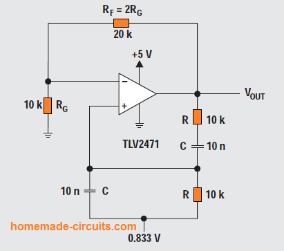
Wien-bridge circuit
The below given diagram shows the Wien-bridge circuit setup.
Here, we can break the loop at the positive input of the opamp and calculate the returning signal using the following Equation 2:
When ⍵ = 2πpf = 1/RC, the feedback is in phase (positive feedback), having a gain of 1/3.
Therefore the oscillations needs the opamp circuit to have a gain of 3.
When RF = 2RG, the amplifier gain is 3 and oscillation initiates at f = 1/2πRC.
In our experiment the circuit oscillated at 1.65 kHz instead of 1.59 kHz using the indicated part values in Figure 3, but with an apparent distortion.
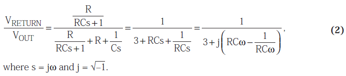
The next figure below demonstrates a Wien-bridge circuit having non-linear feedback.
We can see a lamp RL whose filament resistance is selected very low, about 50 % of the feedback resistance value of RF, since the lamp current is defined by RF and RL.
The relationship between the lamp current and lamp resistance being nonlinear, helps to keep the output voltage variations at the minimum level.
You may also find many circuits incorporating diode instead of the above explained nonlinear feedback element concept.
The use of a diode helps decrease the distortion level by offering a gentle output voltage control.
However if the above methods are not favorable to you then you must go for AGC methods, which identically helps to get a reduced distortion.
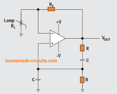
A common Wien-bridge oscillator using an AGC circuit is displayed in the following figure.
Here, it samples the negative sine wave by means of D1, and the sample is stored inside C1.
R1 and R2 are calculated such that it centers the bias on Q1 to ensure that (RG + RQ1) equals RF/2 with the expected output voltage.
If the output voltage tends to get higher, resistance of Q1 rises, consequently lowering the gain.
In the first Wien bridge oscillator circuit, the 0.833-volt supply can be seen applied on the positive opamp input pin. This was done in order to centeralize the output quiescent voltage at VCC/2 = 2.5 V.
Phase-shift oscillator (one opamp)
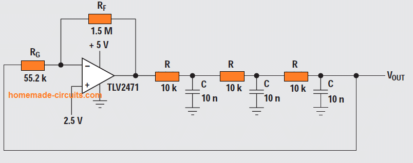
A phase-shift oscillator circuit can be also constructed using just a single opamp as shown above.
The conventional thinking is that in phase-shift circuits the stages are isolated and self-governing of one another. This gives us the following equation:
When the phase shift of individual section is –60° the loop phase shift is = –180°. This happens when ⍵ = 2πpf = 1.732/RC since the tangent 60° = 1.73.
The value of β at this moment happens to be (1/2)3, which means that the gain, A, has to be with a level of 8 for the system gain to be with a level at 1.
In this diagram the frequency of oscillation for the indicated part values was found to be 3.76 kHz, and not as per the calculated oscillation frequency of 2.76 kHz.
Moreover, the gain necessary to initiate oscillation was measured to be 26 and not as per the calculated gain of 8.
These kinds of inaccuracies are to some extent due to component imperfections.
However the most significant affecting aspect is due to the wrong predictions that the RC stages never impact one another.
This single opamp circuit setup used to be quite well-known at times when active components were bulky and high priced.
Nowadays op-amps are economical and compact and are available with four numbers within a single package, therefore the single opamp phase-shift oscillator has eventually lost its recognition.
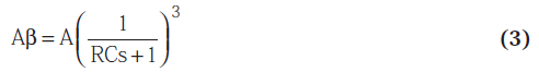
Buffered phase-shift oscillator
We can see a buffered phase-shift oscillator circuit in the above figure, pulsating at 2.9 kHz instead of the expected ideal frequency of 2.76 kHz, and with a gain of 8.33 as opposed to an ideal gain of 8.
The buffers prohibit the RC sections from affecting each other, and therefore the buffered phase-shift oscillators are able to operate closer to the calculated frequency and gain.
The resistor RG responsible for the gain setting, loads the third RC section, allowing the 4th opamp in a quad opamp to act as a buffer for this RC section. This causes the efficiency level to reach an ideal value.
We can extract a low-distortion sine wave from any of the phase-shift oscillator stages, but the most natural sine wave can be derived from the output of the last RC section.
This is usually a high-impedance low current junction, therefore a circuit having a high-impedance input stage must be used here to avoid loading and frequency deviations in response to load variations.
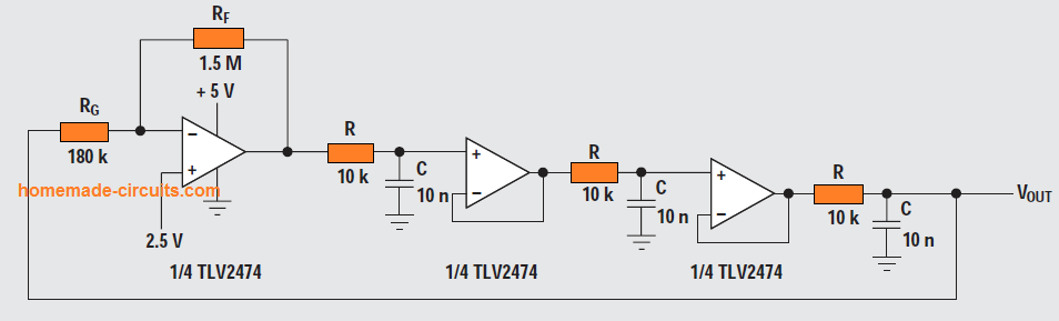
Quadrature oscillator
The quadrature oscillator is another version of phase-shift oscillator circuit, however the three RC stages are put together in a way that every section adds up 90° of phase shift.
The outputs are named sine and cosine (quadrature) simply because there exists a 90° phase shift among opamp outputs. The loop gain is determined through the Equation 4.
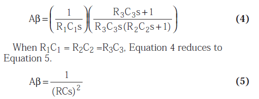
With ⍵ = 1/RC , Equation 5 simplifies to 1√–180°, leading to oscillations at ⍵ = 2πpf = 1/RC.
The experimented circuit pulsed at 1.65 kHz as opposed to the calculated value of 1.59 kHz, and the difference is mainly due to part value variations.
Bubba oscillator
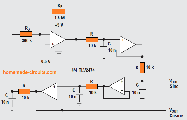
The Bubba oscillator circuit shown above is yet another variant of phase-shift oscillator, but it enjoys the benefit from the quad op-amp package to produce a few distinctive features.
Four RC sections call for 45° phase shift for each section, which means this oscillator comes with an outstanding dΦ/dt to reduce frequency deviations.
Each of the RC sections generates 45° phase shift. Meaning, because we have outputs from alternate sections assures low-impedance quadrature outputs.
Whenever an output is extracted from each opamp, the circuit produces four 45° phase-shifted sine waves. The loop equation can be written as:
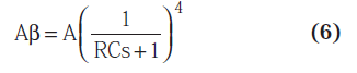
When ⍵ = 1/RCs, the above equations shrinks into the following Equations 7 and 8.
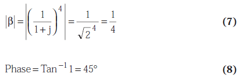
The gain, A, should reach the value of 4 to initiate an oscillation.
The analysis circuit oscillated at 1.76 kHz as opposed to the ideal frequency 1.72 kHz while the gain seemed to be 4.17 instead of the ideal gain of 4.
Due to a reduced gain A and low bias current op-amps, the resistor RG responsible for fixing the gain doesn't load the final RC section. This guarantees the most accurate oscillator frequency output.
Extremely low-distortion sine waves could be acquired from the junction of R and RG.
Whenever low-distortion sine waves are needed across all the outputs, the gain actually should be distributed equally among all the opamps.
The non-inverting input of the gain op-amp is biased at 0.5 V to create the quiescent output voltage at 2.5 V. Gain distribution necessitates biasing of the other opamps, but it surely does not have any impact on the frequency of oscillation.
Conclusions
In the above discussion we understood that Op amp phase shift oscillator circuits are constrained to the lower end of the frequency band.
This is due to the fact that op-amps don’t have the essential bandwidth for implementing low phase shift at higher frequencies.
Applying the modern current-feedback op-amps in oscillator circuits look difficult since these are very sensitive to feedback capacitance.
Voltage feedback op-amps are restricted to just a few 100 kHz since they build up excessive phase shift.
The Wien-bridge oscillator works using a small number of parts, and its frequency stability is very acceptable.
But, toning down the distortion in a Wien-bridge oscillator circuit is less easier than initiating the oscillation process itself.
The quadrature oscillator surely runs using a couple of op-amps, but it includes much higher distortion. However, phase-shift oscillators, like the Bubba oscillator exhibit much lower distortion along with some decent frequency stability.
Having said this, the enhanced functionality of this type of phase-shift oscillator circuit does not come cheap due to higher costs of the parts involved across the various stages of the circuit.
Related Web sites
www.ti.com/sc/amplifiers
www.ti.com/sc/docs/products/analog/tlv2471.html
www.ti.com/sc/docs/products/analog/tlv2472.html
www.ti.com/sc/docs/products/analog/tlv2474.html

Comments
Hey, If you give your email id then better for me. Is it possible to give you your email??
It is
hitman2008
@
live.in
Hey, I am Linkon. I have one problem regarding one opm ckt. Could you help me
Without seeing the schematic I can’t say whether I can solve it or not!
Actually, this is my university project that’s why I am scared to share this place. IF you give your email id then better for me.
Sorry, without sharing the schematic publicly it may not be possible for me to provide any suggestions.
Hey, Thank you for your feedback. I am trying to post in my project.