In this post I have explained a relay cut-off circuit which may be included in inverters to ensures that under a no load at the output the condition is quickly detected and the supply cut off, preventing the inverter from operating unnecessarily. The idea was requested by Mr. Rajath.
Technical Specifications
I need to adopt a no load auto cutoff system into my inverter, do you have any suitable design, which could help me. or else can you give any idea on how to achieve ,as i need to shut down the output of the inverter when ever there is no current drawn from it. please help me ,here.
Regards Rajath
The Design
In a few of ay previous posts we have learned how to make overload cut off circuit such as:
Low Battery Cut-off and Overload Protection Circuit.
Motor over current protector circuit
However, the present concept deals with an opposite situation wherein a no load condition is supposed to be detected and cut off for persisting, that is I have explained a circuit for preventing a no load condition for inverters.
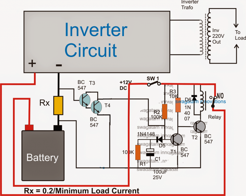
As shown in the above figure, a no load detector and cut of procedure can be initiated by incorporating this design in any inverter circuit.
The operational details may be understood with the following explanation:
The circuit comprises two stage, namely the current amplifier and sensor stage using the T3/T4 Darlington pair, and a simple delay ON stage using T1, T2 and the associated components.
As soon SW1 is switched ON, the delay-ON timer counting is initiated through C1 which begins charging via R2 and D5 keeping T1 switched off in the process. With T1 switched T2 is switched ON which in turn switches ON the relay.
The relay enables the positive from the battery to get connected with the inverter so that the inverter is able to start and generate the required AC mains to the intended appliances.
With the presence of a load at the output the battery undergoes a proportionate amount current consumption, and in the course Rx experiences a current flow through it.
This current is transformed into a proportionate amount of voltage across Rx which is sensed by the T3/T4 Darlington pair and it is forced to switch ON.
With T3/T4 switched ON, C1 is instantly inhibited from getting charged, which leads to an immediate disabling of the delay ON timer, making sure that the output of the inverter continues to supply the voltage to the load.
However, suppose the output of the inverter is devoid of any load (no load condition), T3/T4 is then unable to switch ON, which allows C1 to get charged gradually until the potential across it becomes sufficient to trigger T1.
Once T1 is triggered, T2 is cut off and so is the relay. With the relay contacts cut off and shifted from N/O to the N/C contact, the positive to the inverter is also cut off, the system comes to a stand still.


Comments
hello sir, i would like to ask some few question about this project
1)the darlington transistor are connected at the negative terminal of the battery how is that possible to work? i cant a clear picture about the current flow of this circuit
2)if there are designing calculation for the circuit analysis pleas help me with them
thanks in advance
hello Bady, the Rx resistor needs to be in series with the supply, regardless of the position a voltage will be developed across it whenever the load is switched ON, in the shown design since the current is entering from top of the Rx, the (+) voltage is developed at the base of the associated T3 transistor.
Can this circuit work along side your Low Battery Cut-off and Overload Protection Circuit on an inverter, since both circuits would be on the dc side of the inverter.
yes both can work together, the second sensing resistor could be added in series with the above Rx for sensing overload.
your welcome sir.
What is the purpose of the Rx?
what is the right value for the Rx sir?
Rx is for generating the triggering voltage for the associated Darlington transistor
Rx could be 0.2/1amp = 0.2 ohm
Sir, one more question what will be the the value of Rx?
I don't have an idea about that hope you could help me.
Thanks in advance…
Angelous, The formula for evaluating Rx is given in the diagram..
Sir what a really good circuit.
When this circuit conected to the inverter, it can't affect the efficiency and working performance of the inverter?
Thanks Angelous, No it will not affect the inverter performance…
dear swagatam,
i have a 10 kv inverter wih 15 batteries ie , 180volts.
can you suggest me the switch, relay and Rx rating
dear chandan,
10000/180 = 55 amps, therefore the switch and the relay wil need to be rated at 60 amp minimum…T2 will need to be upgraded to TIP122
Rx will depend upon the intended minimum wattage at which the inverter may be required to be operative.
Hello sir
Can I pass a weak pwm signal into a MOSFET driver like a tc4427 and then use it to drive another full bridge driver IC like the ir2110.
Basically can I drive a MOSFET driver with another MOSFET driver?
no that won't be a good idea…I not able to simulate it in my mind.
By the way it will have a 24v supply for the inverter
Hello sir
Also I have been trying to see if I can come up with an overload/ surge circuit using the delay circuit concept above. Here what I intend to achieve
1) the circuit should have a standard 1500w (full load)reference current or voltage.
Then when we power up a load that is higher than 1500w say 1505w or 1550. As a matter of fact anything from 1501w, instead of indicating an overload immediately it should allow for a minimum amount of time maybe 10secs and then if the load is still at a wattage higher than 1500w it then trips off.
Remember I said I wanted surge ability for loads that require more starting current so now if we power a load that will go as high as say 3000w surge technically it is higher than 1500w and so the circuit delays tripping off overload signal for maybe as usual 10secs and then if after 10secs the load has not droped to its normal power consumption of say 500w then it trips off.
Hope you get what am trying to do here.
Am hoping the circuit can have like a reset button too.
Helo Michael, you can incorporate any of the shown techniques in the following article, and add a 100uF capacitor across base/emitter of the transistor for the delay effect:
https://www.homemade-circuits.com/2014/06/simple-current-sensor-circuit-modules.html
Hello sir
For this delay circuit I can use a 24vdc input I will only increase the relay rating and double the value of the resistors to limit current?
I then use a 12v regulator to power the circuit after the relay.
Hello Michael, that will do.
Hello sir
Sir if I input 24v to the lm338 and set an output voltage of 12v.if the voltage falls to 20v will the ouptut 12v from the regulator also fall?
Hello Micheal, no that'll not happen…as long as the input is at least 3V above the set output voltage, you can be sure of the getting a constant voltage as per the set level.
Also sir
Pls what software do you use to draw those schematics?
Hello Michael,
you'll need to connect 10 ohm individual resistors in series with each gate of the mosfets…it does not have to be 30 ohms
780X are rated to deliver 1 amp…so you can can divide this with IC's current specs to get the
Also sir
How many IC's can a 780X regulator power at a time.
Hello sir
Question about gate resistors.
If I use say a 10 ohm resistor say for a push pull and I have just one resistor on each side.
Now if I parallel say 3 resistors on each side does that mean I use 30 ohm resistors for each mosfet so that the each three MOSFETs in parrell now have 10 ohm resistors when we use the parallel resistor formulae.
I use coreldraw
Hello sir
I am looking at this IC hip4081A it's a full bridge driver as I don't want to use two ir2110.
Sir do you have any experience with this driver?
It can give out up to 2.5A peak current.
Hello Michael, I have not yet studied this IC so I won't be able to suggest much about its operational details, by the way did you check out its datasheet?
You can see it here:
https://www.intersil.com/content/dam/Intersil/documents/hip4/hip4081a.pdf
Morning sir, I am a final yr undergraduate am working on an automatic changeover switch with wireless generator control abilities.. Please I need information thankzzz….. oduduj@gmail.com
Hi Odudu, please provide more info regarding your requirement, by the way i may be having this circuit already in my blog….
Hello Sir,
So if am right by your explanation then it means that
When the circuit is on T1 base voltage is grounded due to the capacitor charging and this allows a base voltage at T2 thereby switching it on and allowing the really to be switched on.
Now when load is significant voltage is present at T3 and T4 base which then halts the capacitor charging.
2) the delay time formulae is t = 1.1RC right?
3) I also noticed that C has to be large enough to effectively ground voltage at base of T1?
Hello Michael,
yes that's correct, but a "significant" voltage or current is not required, the operation can be assumed to initiate even with a small load at the output, and that's what the circuit is intended to be like. This can be set by calculating Rx correctly.
I have not yet checked the formula, it could be correct, but is not important as the value of R2, C1 can be fixed with a little trial and error.
C does not have to be large, because we want the changeover to take place quickly so basically it should be relatively smaller.
Hello sir,
Nice and simple concept
I have a few questions though. While mind simulating the circuit I want to ask
1) "under signigicant load" when huge currents flow through Rx which converts to proportional voltage and then the Darlington pair(T3 and T4) is triggered with sufficient voltage at its base this should ground the voltage at the base of T1 which leads to having a voltage at the base of T2 which triggers T2 and therefore stops the relay from working right?
2) how will the capacitor trigger T1 though the diode
Hello Michael,
thanks!
1) with T1 switched OFF, T2 is allowed to be switch ON, which in turn keeps the relay ON. The relay contacts in this situation connect across the N/O allowing the inverter to operate.
so in the presence of load, the relay is allowed to remain activated.
2) the capacitor while charging pulls the T2 base voltage to the ground level, until it has charged to a point where the base voltage at T1 is able to reach above the 0.6V mark, and at this point T1 switches ON.