In this article I have explained how to build an automatic battery charger circuit using dump capacitor concept for self detecting and charging a multiple set of batteries. The idea was requested by Mr. Michael.
Circuit Objectives and Requirements
- My name is Michael and live in Belgium.
- I found your site thru google during my search of a battery trickle charger.
- I've checked all 99 battery chargers but couldn't find one that maintains multiple batteries.
- I'm still looking for a good circuit, therefore I hope maybe you can help me out.
- At home we have a variety of lead acid batteries and during the winter most of them get neglected.
- Resulting in spring, a check which battery made it and which one didn't.
- Problem is the variety of batteries I'm a biker, my brothers has a small excavator and tractor, we have 2 vans with 2 caravans and we ( I, mother, sister, 2 brothers and there girlfriends) all have a car.
- So you see a WIDE variety of batteries, in the past I've bought a smart 7stage charger but it is impossible to take care of all batteries using only one charger.
- So I ask if you could design a circuit for me.
- With the following specs:
- Maintain at least 5 or more batteries simultaneously.
- Checks voltage if low dumps a capacitor into the battery.
- Able to handle capacities as low as 3 Ah up to 200Ah.
- Safe to operate 24/7 with no user input.
- Some of the things I've given some thought:
- With the use of a cap dump, there's no need for a heavy mains transformer, because the load for transformer is under control.
- A selectable capacitor depending on the capacity of the battery.
- A problem for me was to find something that could activate multiple outputs on a time base(using a lm311 to sense the voltage, a 555 to dump using mosfet).
- An indicator of some sort, which will indicate which battery needed the most dumps or immediate dumps, and locate bad batteries.
- If you believe I've made some errors, or my requirements are impossible please let me now.
- If you could implement extra features or safety features, I didn't think of do not hesitate to add or modify:)
- I'm a student getting a bachelor in Electro Mechanics, I'm a electronic enthusiast, have a room full of components and parts to play with.
- But I lack the designer skills for building circuits for my needs.
- I hope to have drawn your interest in this problem and hope you find the time to design something for me.
- Maybe this circuit could become number hundred on your site!
- Also great job with your site and hope al the best for you!
The Design
The discussed circuit concept for automatically charging multiple batteries using dump capacitor can be fundamentally divided into 3 stages:
- opamp comparator detector stage
- IC 555 ON/OFF interval generator
- dump capacitor circuit stage
The opamp stages are configured to maintain a continuous sensing of battery charge level, and correspondingly execute the cutoff /restoration of the charging process across the batteries attached with their relevant inputs. The charging process is carried out through capacitor dump system.
Let's undersatnd the various stgaes elaborately:
Self Regulating 4 Battery Opamp Charger Circuit
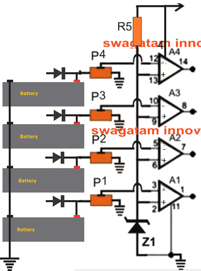
The first stage within this design is the opamp battery over charge detector circuit, the schematic of this stage can be seen below:
Parts List:
opamps: LM324
presets:10K
zener 6V/0.5 watt
R5 = 10K
diodes = 6A4 or as per the charging specs
We will consider only 4 batteries here, and therefore use 4 opamps for the respective over charge cut offs. A1 to A4 opamps are taken from the quad opamp IC LM324, each configured as compartaors to detect the attached corresponding battery over charge levels.
As can be seen in the diagram the non-inverting inputs of each of the opamps is configured with the relevant battery positives for enabling the required sensing of the battery voltages.
The positives of the individual batteries are connected with the capacitor dump output, which I will elucidate in the later part of the article.
The inverting (-) pins of the opamps are designated to a fixed reference level through a single common zener diode.
The presets attached with the (+) or the non-inverting inputs of the opamps and are used for setting up the precise full-charge trip points with respect to the corresponding (-) pin zener reference levels.
The presets are set such that when the relevant battery voltage reaches the full charge level, the proportionate value at the pin(+) of the opamp just goes above the (-) pin zener reference level.
The above situation instantly turns the opamp's output from its initial 0V to a high logic equal to the supply voltage level.
This high at the opamp output triggers an IC 555 atable circuit so that the IC 555 is enabled to produce a periodic ON/OFF intervals over the attached capacitor dump circuit...the following discussion have explained us the proceedings:
IC 555 Astable for Generating periodic ON/OFF
The following schematic shows the IC 555 stage configured as an astable for the intended periodic ON/OFF switching generation for the subsequent capacitor dump circuit.
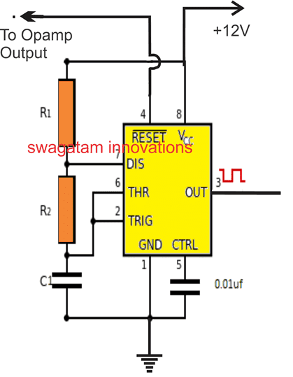
Parts List
IC = IC 555
R2 = 22K
R1, C2 = calculate to get the desired charge dump cycle rate
As shown in the above diagram, pin#4 which is the reset pinout of the IC 555 is connected with the output of the relevant opamp stage.
Each of the opamps will have its own separate IC 555 stages along with the capacitor dump circuit stage.
While the battery is in the charging process and the opamp output is held at zero, the IC 555 astable stays disabled, however the moment the relevant attached battery gets fully charged, and the concerned opamp output turns positive, the connected the IC 555 astable becomes activated, which causes its output pin#3 to generate a periodic ON/OFF cycles.
The pin#3 of the IC 555 is configured with its own individual capacitor dump circuit, which responds to the ON/OFF cycles from the IC 555 stage and begins the process of charging and dumping a capacitor across the relevant battery.
To understand how this dump capacitor behaves in response to the IC 555 ON/OFF cycles we may have to go through the following section of the article:
Capacitor Dump Charger Circuit:
As per the request the battery is required to be charged through a capacitor dump circuit, and I came up with the following circuit, I hope it would do the job as per the expectations:
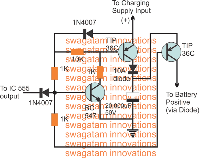
The circuit functioning of the above shown capacitor dump charger circuit can be learned following explanation:
- As long as IC 555 stays in the disabled state, the BC547 is allowed to get the required biasing through its base 1K resistor, which in turn keeps the associated TIP36 transistor in the ON position.
- This situation allows the high value collector capacitor to get charged to its maximum allowable limit. In this position the capacitor is armed in the charged stand-by position.
- The moment IC 555 stage gets activated and begins its ON OFF cycle, the OFF periods of the cycle switches OFF BC547/TIP36 pair, and switches ON the extreme left side TIP36, which instantly closes and dumps the charge from the capacitor into the associated battery positive.
- The next ON cycle from the IC 555 reverts the situation into the previous conditions and charges the 20,000uF capacitor, and yet again, with the next subsequent OFF cycle the capacitor is allowed to dump its charge via the relevant TIP36 transistor.
- This charging and dumping operation is carried out continuously until the corresponding battery becomes fully charged, forcing the opamp to turn OFF itself and the whole proceedings.
All the opamps work in the similar manner, by sensing the attached battery condition and self starting the above explained procedures.
This concludes the explanation regarding the proposed automatic multiple battery charger using capacitor dump charging, if you have any questions or doubts, do not hesitate to communicate through comments...


Comments
Hello
I am a noob in regards to this but would like to try an make a suggestion.
Due to the cost of the cap, can a common cap for all batteries be used an the transistor be triggered by the sensing circuit? This way we can cut the cost of this project allot.
Hello, the capacitor used is a standard or common electrolytic capacitor, it is not a super-cap or any other special type.
The capacitor must be switched ON/OFF in order to create the dump/charge effect, if it’s directly connected with the opamp output the dump/charge action will not happen and the circuit will not function as it is designed to function.
Good Day Sir,
can this charger charge a li-ion battery? and do you have a balancing charging circuit for multiple li-ion battery? pls can you provide me a link sir..
thank you very much sir..
Paul
Hi Paul, yes it can be used for charging any type of battery, just make sure to charge the capacitor with the right amount of current, depending on the battery type.
for Li-ion use the full “1C” current which may be equal to the batt’s AH rating, to charge the capacitor.
a balance charger must be used only if the batts are connected in series, you can refer to the following article:
https://www.homemade-circuits.com/lipo-battery-balance-charger-circuit/
hi swagatam.can u help me make an automatic battery charger with adjustable voltage and current, charging and full charge indicator,and can charge lead acid 6v and 12v batteries.these are my components:transformer 220ac,12 amps.12-0,capacitor 4700uf,16v electrolytic,diode 1n5400.looking forward.thnx.
Hi, Michael here,
Many thanks for the design and the quick response, I’ve got a few questions and suggestions;
On the first image I see a diode attached to positive terminal of the battery what is its purpose?
Also by using the pots P1 to P4 it would be best to use high resistive pots, maybe even split them up with fixed resistors .
Is there a way to prohibit multiple dumping of the different caps? In a way like:
Batt1 ok no dump; Batt2 nok dump; Batt3 ok no dump; Batt4 ok no dump; repeat cycle;1234, 12…
I believe it would be the easiest way to alter the duty-cycle of the 555 to be sure de caps are fully charged before dumping?
An extra sensing circuit to control the voltage of the caps would make the circuit to complicated?
Sincerely
Michael
Hi Michael, here are answers to your questions:
1) The diode ends (anodes) will connect with respective dump capacitor outputs or the collector of the right side TIP36 transistors.
you can use a high value resistance pots, but the value is not relevant because the opamp inputs have a high impedance, and it is the ratio across the pot slider arm that actually matters not the value…still a high value can be good as it will help reduce power drain across the pots.
same cap is not used for all the batteries….each battery is supposed to have a separate dump capacitor stage, linked with the diode of the battery positive, so each dump capacitor stage will work separately for their allocated batteries.
therefore each battery will be sensed separately and charged separately.
The IC 555 will be immediately switched OFF and rendered inactive as soon as the relevant battery is found to be charged, therefore capacitor dump cannot happen if the battery is fully charged.
By the way even if the the capacitor was allowed to dump, it will not be able to pass its charge into the battery if the battery is fully charged, the capacitor will have to retain the charge inside itself, because the battery will not accept anything extra.
Hi good day mr swagatam.. let me ask you.. please help me about this.. I have a power transformer which is have output of 33v and 36amps, input 220 v. I want this to be an inverter to provide a current to my household, can you please provide me a circuit and the solar pv to be used? Please please please
Hi Mark,
Please provide the following information which will help me to advise correctly:
1) Is it a center tap trafo or a 2 wire trafo?
2) what type of output do you require, a square wave, modified square wave or a sine wave?
Also note that for a 36Amp full current operation you may require a 200 AH battery.
Hi Swagatam,
guten morgen.eine sehr schöne schaltung und nicht kompliziert oder mit mikroprocessor.
viele grüße
walter
Danke Walter, ich bin froh, dass es dir gefallen hat …