In this post I have explained a simple mosquito electrocution net, or mesh circuit which can be easily built and installed on a home window for blocking and killing an in-surge of mosquitoes. The idea was requested by Mr. Ram.
Technical Specifications
Please help with any working circuit diagram for Mosquito, Insect Killer using Walton Voltage multiplier method. Output should be around 2kv. I want to let it remain connected in ac mains like 'Insect Killer cum Night Lamp' which are available on market but they are having 900-1000v in output and stop working in few days.
I tried to get help from Google but I am getting negative feedback most of the time. People are saying they are getting dropped voltage at output. You have some circuits, but they are battery operated and can't remain on all the times.
Please help with with a new topic on this format.
Regards
Ram
The Design
Warning: The circuit design explained below involves a very high voltage, extreme caution is advised while testing and using the unit for the application.
In one of the earlier posts we discovered how conventional mosquitoes traps work by luring the insects through the generation of CO2 gas (by burning propane gas), and other other forms of agents such as octenol which imitate human respiration and human body odor respectively, and help to attract mosquitoes towards these artificially generated baits.
However since there's no easy way of manufacturing CO2 at home, neither is acquiring octenol for the same, attracting mosquitoes the usual way looks to be the most hassle free option.
The natural way is the manner in which we find the mosquitoes enter our houses everyday in the evening, by tracking the CO2 content generating by us in our house and also by the body odor that may be consistently present inside our homes.
Also since the entry path of the mosquitoes is usually through the windows, this entrance can be effectively used for installing a trap and for killing the insects.
The idea here is to position a set of steel meshes covering a particular selected window, and powered with a high voltage source. When the mosquitoes try to make their way through this window, they are instantly killed through electrocution between the mesh structures.
I have already discussed the mechanism and a working circuit of a mosquito zapper bat in one of my previous posts, which utilized a high voltage generator for electrocuting the insects trapped in the bat mesh. The present mosquito killer design is also based on the same principle and makes use of a high voltage across a window mesh for electrocuting the passing mosquitoes.
In one of the other posts I have explained how to make a CDI driver circuit for generating high voltage sparks inside a vehicle spark plug.
Since the above concept facilitates an easy and quick way of implementing a high voltage across a given pair of terminals, we incorporate the same for creating the electrocuting arcs across a set of window mesh assemblies.
The following discussion shows how the mosquito trap or the mosquito killer mesh can be built at home for the suggested purpose.
Designing the Steel Mesh
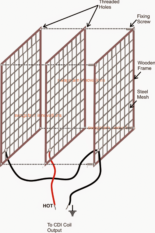
Referring to the shown diagram the mesh assembly is built by fitting three identical sets of readymade fine iron or steel nets with a help of a few well fabricated square wooden frames.
After securing the steel nets within the wooden frames, these are tightly screwed together face to face using nuts and bolts and spacers such that the three frames acquire an optimized distance from each other.
The above assembly actually becomes the most tedious and the crucial part of the system and once this is completed, making the high voltage mosquito killer circuit can be rather simply done with the help of the following circuit.
The High Voltage Generator Circuit
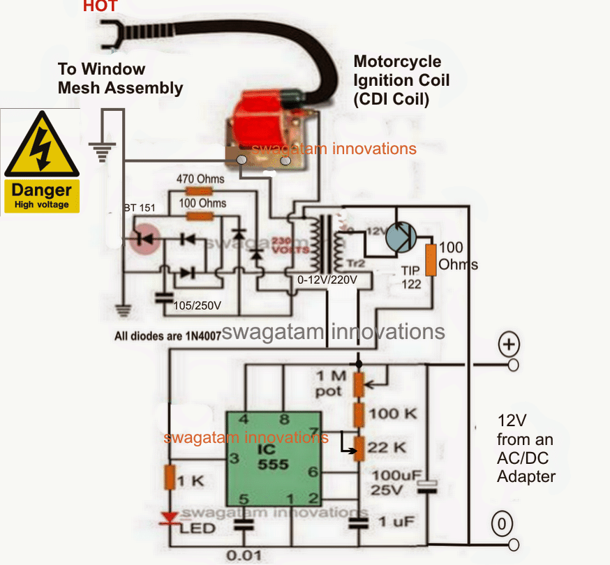
In the above high voltage generator circuit, the IC 555 astable is used for feeding high frequency pulses to the primary of an ordinary 0-12V/220V transformer, via a switching transistor TIP122.
This generates the specified 220V across the other side of the transformer which is used for charging a high voltage capacitor via a network of rectifier diodes.
The accumulated 220V charge inside the capacitor is alternately discharged by an SCR circuit, such that the discharge voltage is dumped across the primary of a standard ignition coil transformer, commonly seen in motorcycles for generating sparks in the spark plug.
The induced 220V in the primary of the ignition coil generates a very high voltage across its secondary high tension wire.
This extremely high voltage is fed across the steel mesh, in the manner as specified in the first diagram.
The central mesh carries the hot end of the ignition coil, while the outer meshes are connected with the ground potential of the circuit.
The 22k of the 555 IC circuit is carefully adjusted such that the sparks do not fly off between meshes as long as there are no interfering elements between the meshes, but trigger thee sparks as soon as a "fly" or a mosquito is detected between the mesh assemblies.
The 100k pot must be used to regulate and produce the best frequency which may ensure reasonably cool running of the two transformers.
The circuit may be powered with any standard 0-12V/1amp adapter unit.



Questions & Answers
Wow
Thank you Sir!
you are welcome Ram!
In above circuit for charge section you provide only CDI. But CDI & COIL is different two section. In diagram only Coil is show by two points. Please help me for this confusion.
the diodes, the SCR and the 105/400V capacitor network forms the CDI circuit, and the red color unit is the CDI coil.
What is the rating of the Transformar(0-12v/230v)
yes that's right….0-12v/220V
Above circuit assemble as per your design but if i connect 100uf capacitor at + & – of battery connection voltage get dropped. When i tested both point by continuity gives my multi meter. when i disconnect this capacitor, it does not happen. Another question is what is voltage across transformer.
When i connect battery led glows and flicker as transformer connected.
For check voltage at transformer my multi meter get fluctuate and spark in meter.
Please suggest what i do? Can i go further for CDI circuit?
the 100uF will never drop the battery voltage…..may be your capacitor is faulty, anyway don't use it's not important.
connect a 10k resistor instead of the 100 ohms at the base of the TIP122 and see the response on the LED.
use the 500V AC range in the meter while checking the 220V transformer winding voltage
i have regular meter having 700v ac volt capacity. what is trim pot role in this circuit?
I made changes now it shows 440 ac volt on transformer and led glows brightly. Now my question is if battery voltage drop 10 to 11 v then it also worked or stopped? What type and rated transformer is used for this circuit? Means 0.5 watt 230-12v transformer is suitable for this circuit?
I used 1watt 2tap transformer which is burnout.
this circuit same is as moscuito bat used in home which cost is arround 100-150INR as compaired to this circuit cost bat is cheap, can we use this readymade circuit for above function which is operated on 3to 6 volt.
at lower battery voltages also the circuit will work but the 440V will drop proportionately.
transformer can be any ordinary iron core step down 0-12V/220V/500mA or 1 amp type.
this is not same as the mosquito bat, this circuit is 10 times more power powerful, because it has to cover a larger area across the window.
bat circuit will not be as effective for the above proposed window net application.
I assemble this circuit I just assemble without cdi coil. I get test result,
1 voltage at transformer 12 volt side is ac 21 volt
2: on other side voltage not shwon by multi meter which range have ac 700 v
3: 100 ohm 1 watt get so hot
Actually I lost one transformer of 1 watt when I connect get sparked and stop working
please help me what I do and if I assemble whole circuit it get beneficial result for field
you must use an ordinary iron core step down 0-12V/220V/500mA or 1 amp type.
100 ohm at the SCR gate should not heat up…something may be wrong in your connections, check it again
Although I have not assemble the circuit, the reason of burning your transformer is because you left it unloaded and voltage may have risen beyond the limit which sparked in winding and get shorted. Never use such type of high voltage circuit without load.
However Mr. Majumdar you have not explained the working of circuit. BT 151 is a triac or SCR, What is the number of diode used.
sorry that's incorrect, the transformer has nothing to do with loading, the transformer will burn only if its operated with excess current than its max specified rating or if it's of poor quality.
The symbol shows that it's a SCR, I have explained its functioning in the other article:
https://www.homemade-circuits.com/2011/12/how-to-make-capacitive-discharge.html
Can you tell me if I can directly supply 12 AC (instead of the DC) to the coil and get a high voltage output without any of the additional circuit elements? How can I do this do I need to put in any other elements like a resistor to limit the current etc?
Thanks.
you can do it by feeding the 12V AC to the right side winding of TR2, where TIP122 collector is connected….then you can remove the entire 555 IC section along with the TIP122
Sir, the transformer is designed for 50Hz, but your NE555 is oscilating at higher frequency than 50Hz, so is the transformer stepup the voltage? What is the frequency comming from NE555 if its udjusted optimal?
Dhanu, a transformer frequency limit is not fixed to 50Hz…it can be increased to some higher levels also, but lower frequencies are better.
The 1M pot is specifically provided for adjusting the frequency to match the frequency performance.
you can use any online 555 calculator for calculating the frequency or use a frequency meter
And I have one more doubt. If the TR2 output is 230v (left side), then why we are using AC/DC adapter, NE555 & TR2? Can we use simple circuit by avoiding above 3 items?
you can simply use another transformer like TR2 and connect it with mains, and connect its output to the input of TR2
Where can I purchase these components,in India,especially,CDI coil.Can you also help us with the abstract?Thanks in advance.
Components can be purchased from any nearest electronic spare part dealer and the CDI coil coil from any 2/3 wheeler spare part store
I want to setup a system to automatically feed my fish. Is there anything but smoke left over to drop into my tank when these critters get zapped?
you can arrange the grids over the tank and allow the insects to get attracted on the grid…
Sir,the CDI coil that is available in "www.amazon.in" looks quite different from the image you have displayed above.Can we proceed further and buy the same?Is it the same one?
the external appearance does not matter, just check the specifications, it should be 100 to 220V at the input and over 2kV at the output
Thanks sir ,
We got the output..
that's great Karthi….thanks
Please give more info about cdi coil' type of transformer' external dc power
source'
And testing of whole project
How i will know that circuit is working?
Thanks
the shown CDI coil is a standard unit which is normally used in 2 stroke or 4 stroke motorcycles and auto-rickshaws
a working design will show sparking (arcing) between the CDI high tension wire and the ground line, when these are brought around at 1cm distance.
this project is not for the newcomers, you will need the assistance of an expert electronic engineer to complete this project
Can I get circuit diagram for flickering circuit of decoration lights
Sir Can you please list all the components used in this circuit as the image is not clear
Please click on the diagram to enlarge it, you will be able to see all the parts clearly
Sir how do we set the value for 1M pot and what is its function?
after fabricating and fixing the net assembly you can carefully adjust the two pots such that the sparks do not fly across the nets in a normal condition… unless bridged with some kind of conducting material
Sir we could not find unpolarized capacitors for the circuit and could only find polarized ones will our circuit still work or would have to make any changes?
Mubasher, the 105/400V must be non-polarized, other two can be polarized type.
Should the capacitor be exactly be 105 uF or can its value be a little different like 100 uF or 120 uF?
105 is not the actual value, it's a code.
105 = 10,00000 pF = 1000 nF = 1uF
therefore 105 = 1uF
I REALLY dig this, hope i muster up the balls to actualy build it. I've not done custom electronics for ages now (and then it was the simple ones), and it will be a task 🙂
I wish you all the best, I am sure you will succeed with this project:)
I am really thankful for such a valueable post.
you are welcome!
SIR Swagatam Good afternoon,
You are the best and best man I have ever seen in the world, You care all your students and others in depth, Sir I really appreciate You always.
Sir I need a circuit of CCTV camera,
DESCRIPTION:-
If someone have ammunition then our CCTV camera would indicate or alarm the spider.
I need this circuit for protecting our city.
Sir I will wait for your reply
Best Regards
God Bless You
Thank you very much Arif, I appreciate your thoughts very much!
A CCTV camera circuit can be quite sophisticated and difficult to accomplish at home unless you have the entire kit and all the sophisticated gadgets for testing it.
Moreover identifying ammunition might require very sensitive metal detectors or X-ray cameras…all these are beyond my range of expertise….so I am sorry I don't think I would be able to help with this design.
Hiiii
This circuit is very usefull
I can not get BT151 any eqvalant ?