A welding machine is an electrical device which is able to generate a very high current at relatively low DC voltages. This high current output can be suitably used for creating the intended welding arcs and welding joints. The welding joint is created by fusing the welding rod on the joint area through a high current shorting generated by the welding machine.
A small welding machine can be built using a few ordinary 5 amp transformers and a few high current bridge rectifiers. I have explained how to do it.
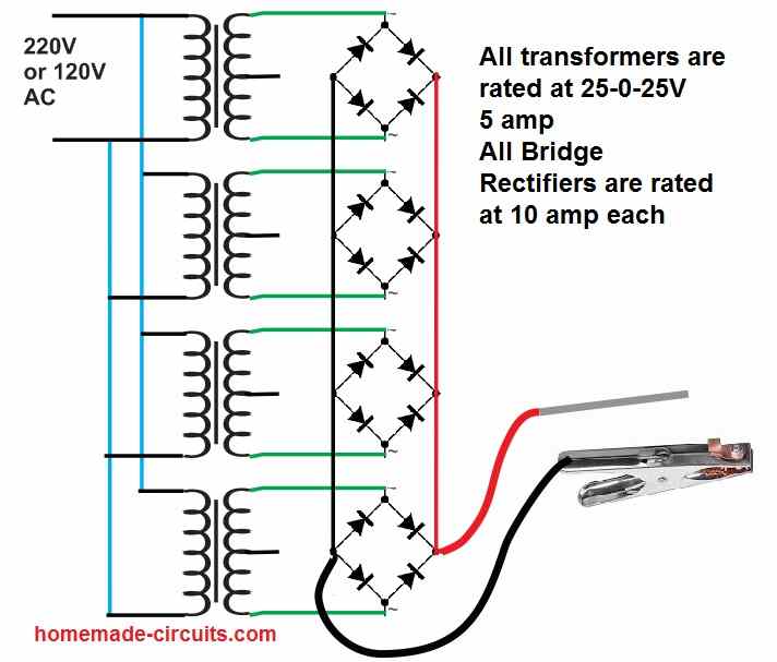
As shown in the following figure, we have used 4 nos of 25-0-25V 5 amp transformer in parallel to generate a reasonably good 20 amp current for the welding purpose.
This is recommended for small welding joints only.
The secondary of the transformers can be seen connected with high current bridge rectifiers in parallel.
The bridge rectifier convert the AC to DC and additionally boost the 25+25 = 50 V into a higher peak level of 50 x 1.41 = 70 V
So overall the output of this small welding machine circuit is able to generate 70 V at 20 amp which is equal to 70 x 20 = 1400 watts of power, enough to create strong welding arcs over small joints.
The bridge rectifiers must be rated at 10 amp each.
Either you can use 10 amp diodes to build the bridge rectifiers or you can ready made 10 amp bridge rectifiers modules for the assembly.
Using Capacitive Method
Caution: The following capacitive welding circuit is extremely dangerous to touch since the entire circuit is not isolated from mains AC and therefore it strictly not recommended for welding purpose.
Read it only for educational purpose and for gaining knowledge about a capacitive high voltage high current generator circuit.
A homemade small scale welding machine circuit is what most of the new hobbyists and mechanical engineers would be looking at for solving their occasional work bench metal welding jobs.
A mini welding machine without using complex circuitry could probably be built using a capacitive power supply as shown in the following diagram:
CAUTION: The mini welding machine circuit shown below is not isolated from mains and has the potentials to kill a person within seconds, therefore extreme caution is advised while handling this equipment in the powered condition.
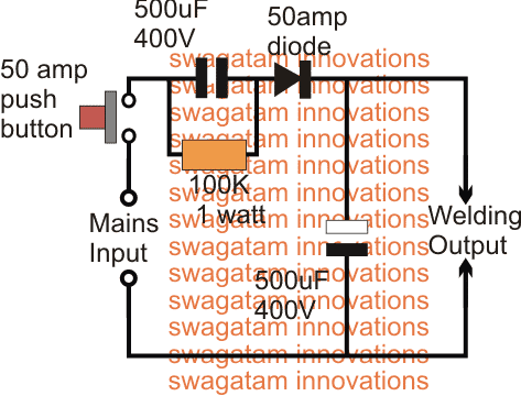
The idea shown above is an ordinary capacitive power supply circuit incorporating extreme capacitors in terms of their values.
Circuit Operation
At the input side we can see a formidable 500uF/400V capacitor, while on the output side also a similar rated capacitor can be seen positioned for reinforcing current.
The most basic parameter essential in a welding system is a high current, so that an extremely high temperature can be formed at the short-circuit junction, over the metal joint in question.
This high current generation can be achieved either by using a high watt transformer or an SMPS version of the same which I have explained in the first paragraph.
A transformer could be too bulky and heavy, while the SMPS circuit too complex for the newcomers, the only alternative way to achieve the high current welding through a relatively simpler design is perhaps by employing the high current capacitive power supply as shown above.
The 500uF/400V capacitor can be expected to generate bursts of current upto as high as 36 amps @ 220V, and reinforced with the complementing output filter capacitor this current can be expected to do some serious welding actions.
You can verify the above mentioned specs by using the following two calculator software:
The shown push button enables the user to achieve the welding job through shorts bursts, and not through a continuous arcing, which can be dangerous, and anyway is not recommended in welding operations.
The input 500uF/400V capacitor looks massive and it might not be readily available in the market, therefore this can be built by using 500 numbers of 1uF/400V PPC capacitors wired in parallel, this could occupy some space, but still the method is easily achievable.
Use Non-Polar Capacitors
This capacitor needs to preferably a non-polar capacitor, however since a diode is positioned in series means an electrolyte capacitor could also serve the purpose without issues.
The second capacitor at the output side can be an electrolytic type for sure.
For more current, the values of the caps could be increased to higher limits, that's the only parameter that needs to be focused on.
Advantage and Disadvantage
The advantage of this circuit is that it is small, cheap, and can be quickly built and used. The disadvantage is that it is very dangerous since there may be AC voltage at the output, therefore you will have to handle the whole system wearing rubber hand gloves.


Comments
Pls sir,is there any chances of electrocution as this circuit is not isolated with transformer.
yes definitely there is…even in transformer based welding machines you will have this danger
Hi sir please show how to make a 0-40v 0-3a smps
you can try the following concept
https://www.homemade-circuits.com/2017/06/12v-2-amp-smps-circuit.html
the Rfbb can be changed for getting different voltages at the output
Hi tun, I do not have asn SMPS version at the moment, however you can build an iron core based auto-transformer for the achieving the results
Hi sir,i need to show me how to step down 230VAC/2A to 150VAC/2A
Hey there,, I have a 470uF 250v cap,, can I use it?
Also what is the component no for 50A diode.? I have 5A diodes, can I put 10 in parallel to achieve 50A??
470uF/250 can be tried and will work as long as the input voltage does not exceed the 250V mark.
please search online regarding "50amp diode" you will be able to find a suitable one.
5A diodes in parallel will not help, and is not recommended
Hi dear,
thanks for your best site,
Inpute voltage is 220 v? How can i use it ?like a welding machine to connect output?
Can melt Iron?
Thank you
yes will do.
50 amp diode is required for rectification.
the 50amp push is a push button which is required to be pushed and released while operating the power supply
Thanks Swagatam,
input is 230 V AC?
560uf 450v can i use?
what is the model 50amp diode?
50 amp push is a fuse?
thank you
Thanks Ali!
This circuit won't melt iron but join iron with the help of welding rod.
just connect the iron which needs to be joined with one of the output terminals, and the other output terminals with a welding rod, now touch the welding rod end at the point on the iron which needs to be fused…