An interesting electronic parasite zapper circuit shown below was successfully built and tested by my friend Mr. Steven. I have explained more about the proposed circuit.
What is a Parasite Zapper
The purpose of this device is simple, it is meant to act like a parasite zapper, a DIY electronic device that people say can push weak electrical pulses through skin electrodes, aimed at killing parasites, pathogens or organisms inside the body.
Also, sometimes it is used for just helping with pain or health issues, that is the claim part.
When you look at it closely, it is basically a low-current pulse generator, and those electrodes are placed on the body. So in simple terms the device is meant to be a low-power electrical pulse generator used with electrodes on skin, claimed by some hobbyists to zap or kill parasites....
The Circuit Idea
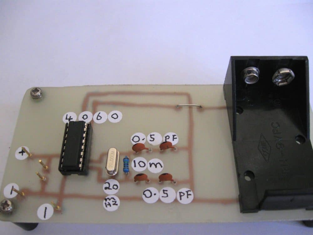
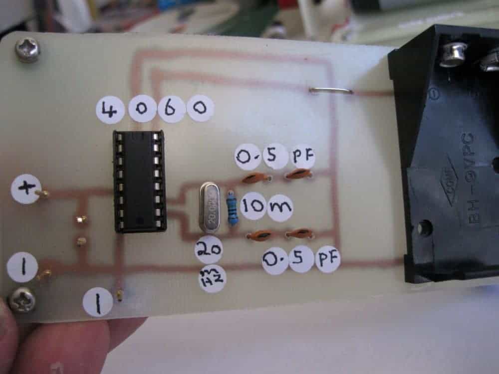
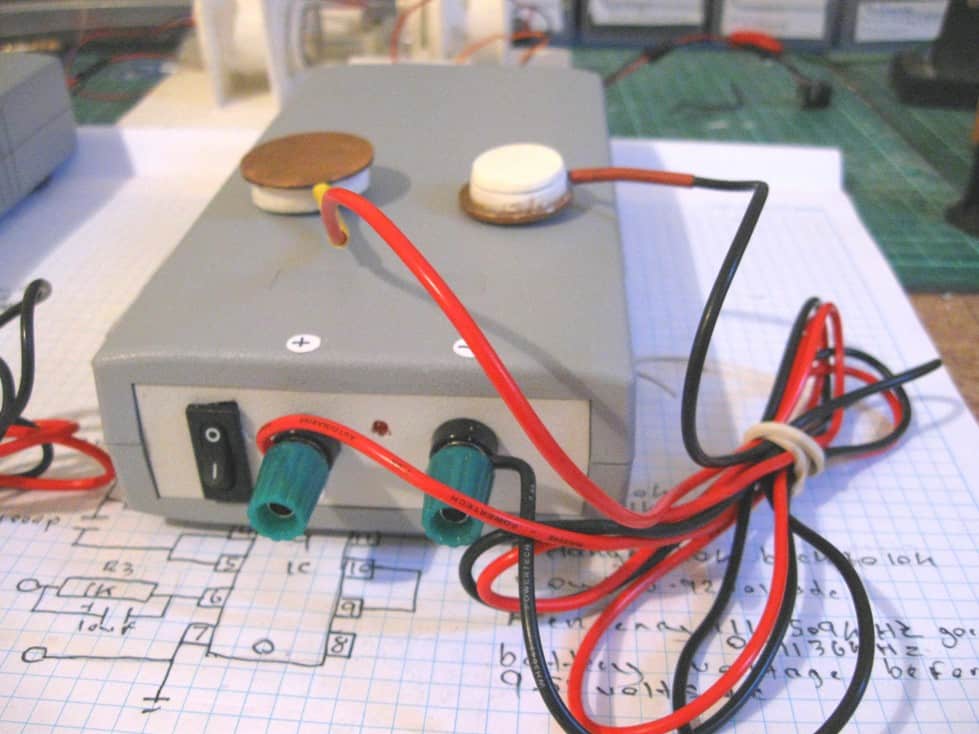
Email received from Mr. Steven: "Hey swagatam did you see the latest pictures I put in my SkyDrive, 4060 integrated circuit type parasite zappers built before but recently installed it into a plastic box enclosure.
The latest one I decided to test on my sore knee, despite having a box full of various ones I built over the years this one I made to pass some free time away and decided to test it out.
I used copper coins for electrodes, each coin was sanded flat on one side with a sharpening stone used for chisel's and knifes, so anyhow the first test I used the coin electrodes on each side of the sore knee joint for a short time.
The next night I decided to try it longer as the pain eased a little the first time, so as I watched TV for about an hour I had the coin electrodes above and below the knee joint, and every few minutes I moved them slightly, during this I noticed a slight pain felt in my knee joint between the coin electrodes, so I thought it odd as I wasn't moving or subjecting any stress to that knee joint.
After a short time the pain went and didn't come back and the next day is the same no pain at all, its all cured and I'm not getting pains trying to stand up or sit down when I bend that knee joint, so that's a great story.
I reckon the small pain may have been a sign that something is working right, now for the back pain I'm getting think it may be a pulled muscle or other."
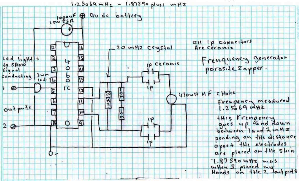
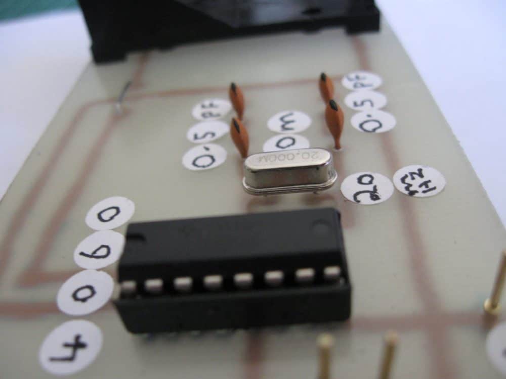
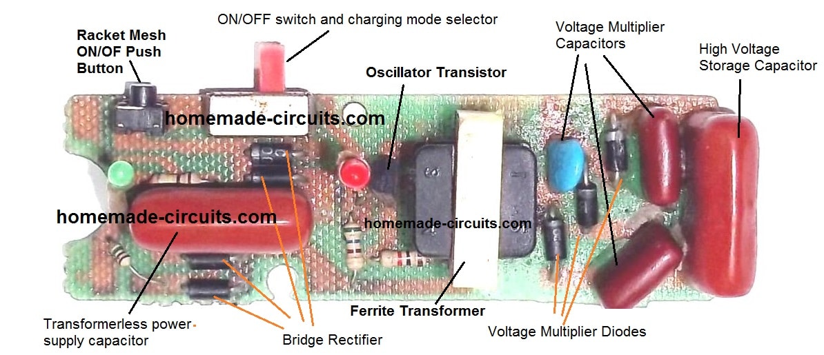
Parasite zapper circuit using IC 4060:
Circuit Diagram
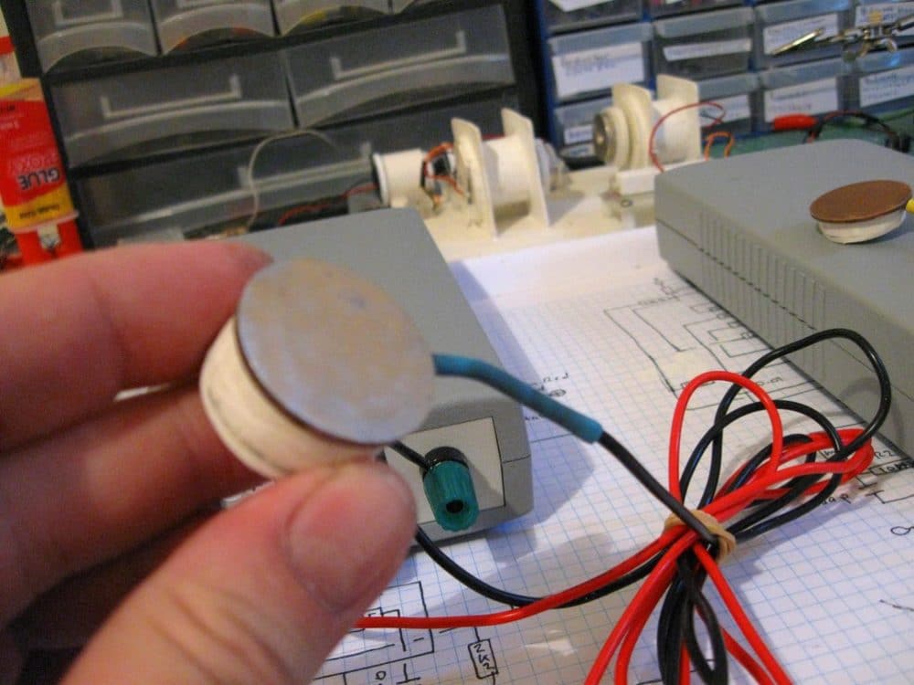
"New copper coin electrodes for my parasite zapper, these are really neat and can be modified to be able to be secured Velcro strap for parasite zapping this is one of a number of pictures I've uploaded to
SkyDrive..."
"My previous designs were based on transistors and other ICs, here are the pics of those previously built parasite zapper models:
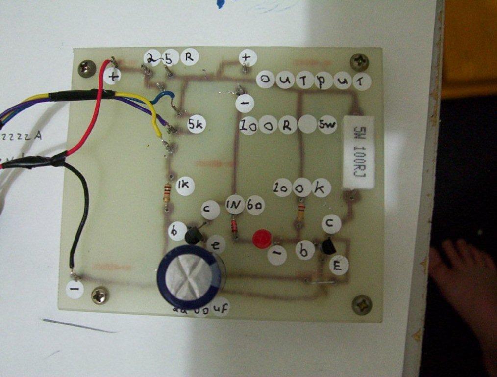
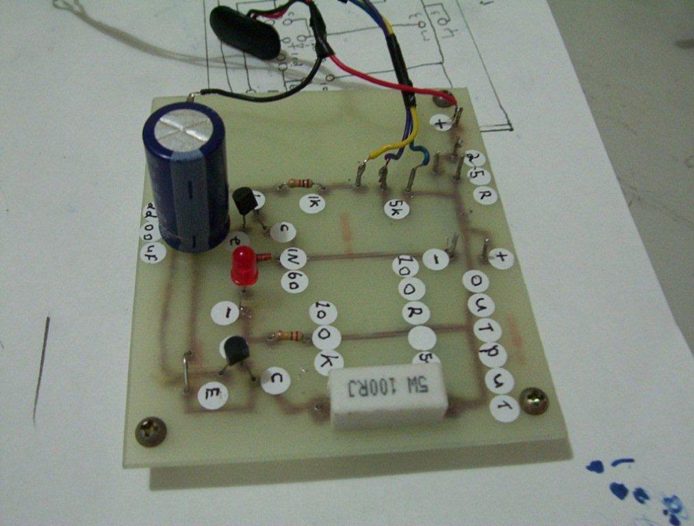
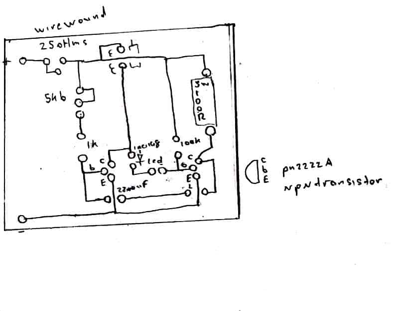
The above is a pulse frequency driver circuit i built from a YouTube video i have made some changes to it i didn't have a bigger size 220uf electro to put into it only small ones so i used the wrong value and put in a 2200uf/35 volts electro, and the 1n4148 diode.
Well it didn't seem to make the LED come on even when powering a motor similar to what the fellow on the net used, so i threw in a 1n60 geranium diode and now the led seems to work some times due some unknown factor, but even without the LED coming on it stills puts out enough voltage to power a motor.
So when the led is supposed to come on for reasons i don't know yet is a mystery i think, at first i wrote the circuit down from the YouTube video then made it onto a bread board and it worked and the led came on when i powered the electric motor.
I have but when i made the printed circuit version and transferred the parts from the bread board onto it the led wouldn't then come on, when i powered the same motor
So i checked the parts on the printed circuit and they all were OK, so i built another bread board one, and it works again even though the printed circuit versions led doesn't come on when i powered the motor the identical circuit on the other works ok very strange.
So its LED comes on too, so i rechecked it on the bread board to find out why it works and not the other, i then found I've mistakenly put in a 1n60 diode so maybe that's why the led comes on when powering a motor.
I changed the 1n4148 diodes on the printed circuit to the same as on the bread board and now the led still doesn't lite up when powering the same motor only some times it blinks when I'm handling the motor due to some unknown factor.
However, despite this they still power the motor and put out enough zap onto my tongue to qualify as an experimental parasite zapper, really i built this from a hand drawn circuit on the net to test on my star ship coils.
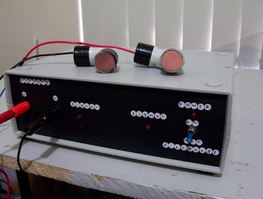
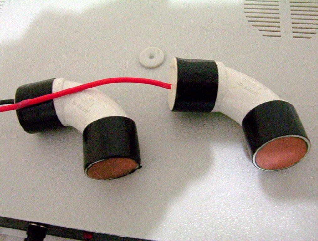
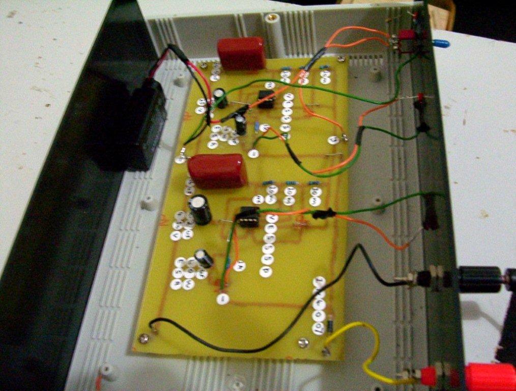
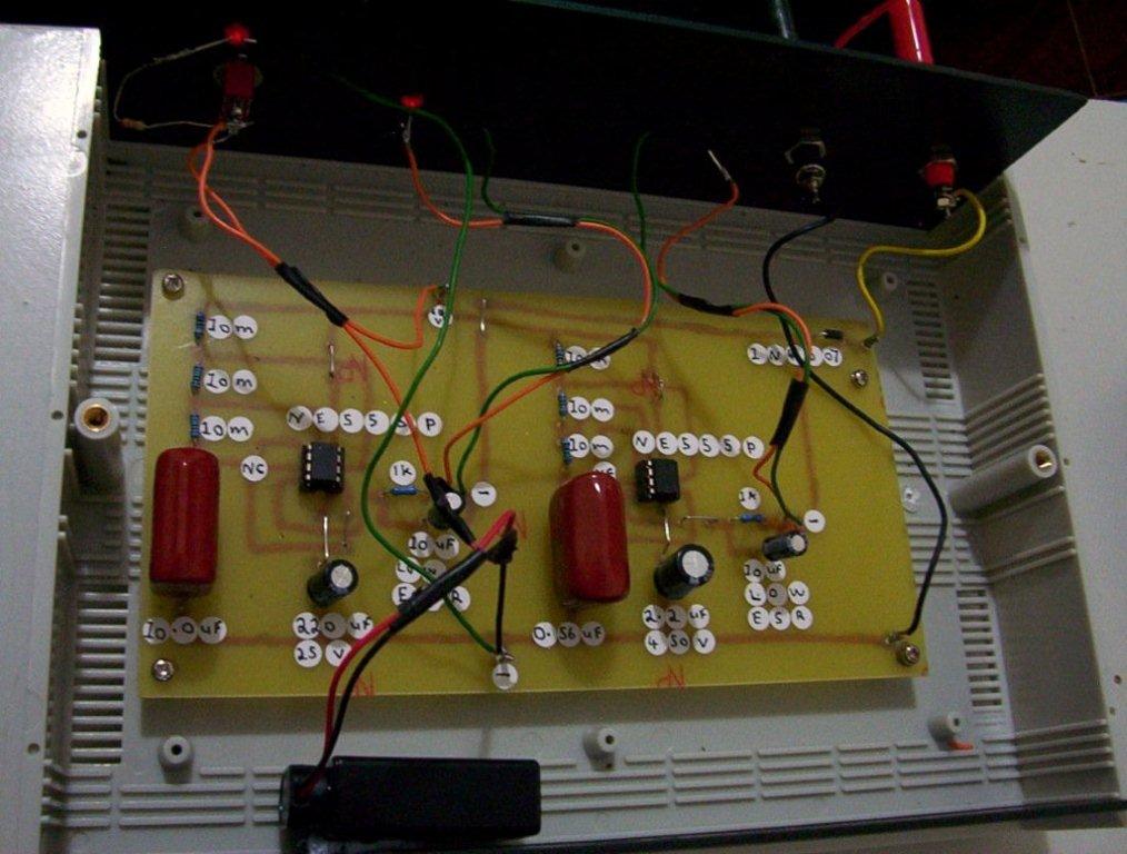
Here's some new pictures of that multi parasite zapper all installed and also the 2 electrodes made from small white pvc elbow joiners used, for pvc pipes.
The actual electrodes are copper 2 cent coins filed flat on one side of each coin so as to provide a good contact with your skin , the best way to avoid that brown tarn that forms on copper surfaces in this case was to use a smear of aloevera gel.
And you can also use aloevera to help the pulses to conduct better into your skin to the aloevera gel does dry out quick or absorb into your skin pretty fast, so its just a matter of applying more aloevera gel to the electrodes or the skin. "
Updates from Steven:
Dear swagatam,
I did an experiment to test this zapper circuit that runs off the 12 volts sla battery, again this time I used my transistor version gravity wave detector to see what else this gravity wave detector can really sense, and to my surprise I got some baffling results like I once did with another parasite zapper I tested a few years ago and used a gravity wave detector circuit as a receiver for anything it may give off in energy or other.
With the parasite zapper hooked up to my slab battery and the headphones plugged into my gravity wave detector I received a high pitch humming like sound the copper pipe hand hold electrodes of my parasite zapper and the positive puts out a stronger energy than the negative.
And I can even tap out morse codes on that positive pipe electrode with my finger and hear it loudly through the headphones as for the negative well its very low sounding.
However, the strange thing is that the sensitive gravity wave detector sensor ceramic capacitor has to be picking something up coming from the positive electrode and it sounds similar to what I get when I slide that copper pipe electrode up and down behind my right ear while holding the negative electrode. So its a bit of a mystery as to what's being given off stronger by just the one copper positive pipe electrode even if the negative is left alone and no contact made to it ,
So with the details of my tests here the parasite zapper is transmitting something that my gravity wave detector can hear and if I cup my hand over near the sensor capacitor the sound is silenced so as if my hand is acting as a shield like it does in some of my sec exciter experiments where the hand put near the gravity wave detector is shielding it from to much rf ac energy in the air transmitted from the sec excitor coil.
In this case with the parasite zapper its a measured dc output voltage so no ac rf involved so how and why the signal is being received from the positive electrode so strongly on the transistor version gravity wave detector is a mystery.
There's no chokes no coils in the parasite zapper, ill try see if there's any rf wave coming from the parasite zapper by using my high sensitivity long range av plug design and my shortwave receiver and ill try using the ac setting on my meter to see if there's an ac component in it to.


Comments
Hello interesting article but can you please tell me what’s a parasite zapper, I’m a bit clueless on this 🙈 is it to zap parasites inside the body and if yes how does it work. Pls excuse the ignorance.
Kind regards Tassnim
Hey, thanks for liking the concept. I have updated the main purpose of the device at the top of the article, please check it…
I find this very interesting – My good friend made a zapper/collidal silver generator for me years ago and unfortunately due to a few strokes – isnt able to do more. I hope to – at some stage build up enough knowledge to be able to build for myself.
May I ask please -and please excuse if it’s a stupid question. You did a zap test on your knee – was the issue with your knee an infection?
Thank you
Thanks, and glad you found the post interesting.
Could you please contact the original author directly through his email and get all the required the info.
Here’s his email ID
stevenchiverton@hotmail.com
In the CD 4060 version of the parasitic zapper, the pitch of the output pin and the specified frequency do not match. Pin 5 is Q5 and divides by 32, 20MHz:32=625kHz. Q4 pin 7 divided by 16 = 1.25 MHz. Based on the manufacturer’s data sheet. Which is the best needle and applicable frequency?
Thanks for the feedback and the corrections.
I have not done the calculations yet, I hope your suggestions are correct.