• Skip to main content
  • Skip to primary sidebar

Homemade Circuit Projects

Need circuit help? Post them in the comments! I've answered over 50,000!

Blog | Categories | About | Contact | Calculators-online
You are here: Home / Grid and 3-Phase / Single Phase Preventor Circuit

Single Phase Preventor Circuit

Last Updated on January 2, 2024 by Swagatam 6 Comments

In this post I have explained a couple simple circuits which when installed will prevent single phase occurrence in a 3 phase system.

Table of Contents
  • Introduction
  • Circuit Operation

Introduction

We all know that for operating heavy electrical loads three phase power or AC is required in order to make the functioning efficient and viable.

However this necessitates the presence of all the three phases at all circumstances. If any of the phases fail, can cause catastrophic consequences to the connected systems. The following artice offers a simple yet effective solution for tacking the above conditions.

As discussed above, a three phase load such as an industrial heavy motor will require the presence of all the three input AC mains phases for reliable and correct operations.

If there's any discrepancy with the presence of the input phases, the motor might start operating under heavily stressful and abnormal conditions.

This might cause huge current consumption, heating of the winding and ultimately burning of the motor parts.

Circuit Operation

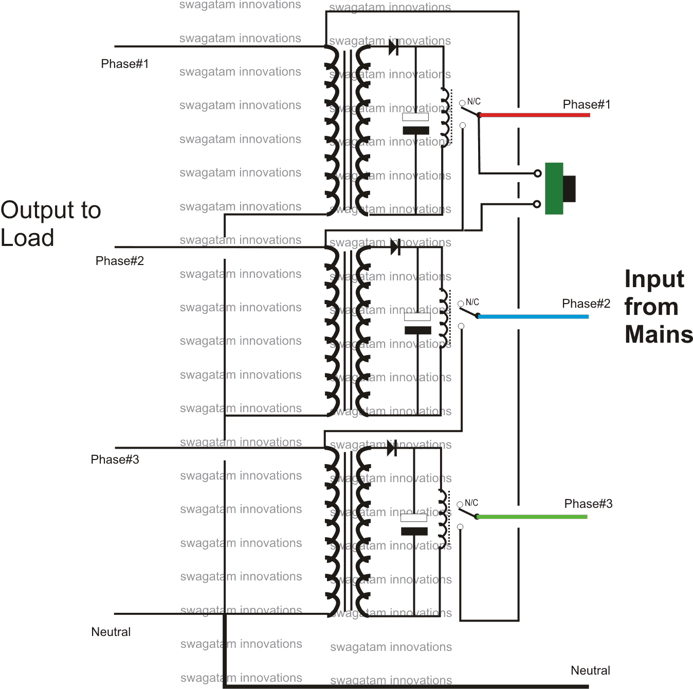
The circuit of a single phasing preventor shown below can be effectively used for eliminating all kinds of undesirable consequences that might result from an abnormal three phase issues.

In the diagram we can see the use of three transformer/relay driver stages.

The transformers can be the normal step-down types, rated appropriately for switching the connected relays.

One of the input primary terminals of all the transformers are made common and connected with the neutral line.

While the other terminals of each transformer are joined to the respective first, second and the third phases of the input mains.

However the above connections are done cleverly via the relay N/O contacts of the subsequent relay assemblies for implementing the required single phasing prevention.

Initially when the set-up is integrated with the the three phases as per the given connections, the phases are remain cut off from the output load, because the relay contacts are all open.

On pressing the given push button, the particular phase in the line is allowed to reach the second or the middle transformer primary winding.

The middle transformer instantly operates its own relay, whose contacts just like the above relay connects the second respective phase with the primary of the bottom transformer, which finally operates its relay powering the top transformer.

Once this happens the entire system gets latched via the N/O contacts of the relays such that now even if the push button is released the system continues and sustains the voltages across the outputs and to the transformers.

Now suppose if any of the phases become low or fails, the particular transformer in line instantly deactivates its relay and the whole system of relays break down in sequence, immediately halting and disconnecting the output loads.

Thus the system effectively prevents the loads from operating under the absence of any of the phases making it sure nothing goes out in fumes.

The circuit was designed exclusively by me, I guess so, if it's already been discovered kindly provide me with the link:

simplesinglephasingpreventercircuit

You'll also like:

  • 1.  Driving 3-Phase Motor on Single Phase Supply
  • 2.  Grid Mains to Generator Changeover Relay Circuit
  • 3.  Arduino 3 Phase Inverter Circuit with Code
  • 4.  Remote Controlled ATS Circuit – Wireless Grid/Generator Changeover
  • 5.  Simple 3 Phase Inverter Circuit
  • 6.  Petrol to LPG ATS Circuit using Solenoid Changeover Valve

About Swagatam

I am an electronics engineer with over 15 years of hands-on experience. I am passionate about inventing, designing electronic circuits and PCBs, and helping hobbyists bring their projects to life. That is why I founded homemade-circuits.com, a website where I share innovative circuit ideas and tutorials. Have a circuit related question? Leave a comment.... I guarantee a reply!

Previous Post: « How Shunt Regulator TL431 Works, Datasheet, Application
Next Post: Single Transformer Inverter/Charger Circuit »

Reader Interactions

Comments

  1. olupot says

    August 20, 2017 at 10:22 pm

    hello sir thanks alot i was successful i finally completed my inverter and it works best.
    i have a question regarding this system yes the tranfo used are stepdown but i want to use a 0-240v primary and 0-12v secondary for powering the relay am i correct there thanks

    Reply
    • Swagatam says

      August 21, 2017 at 3:11 am

      That’s great Olupot, congrats on that!

      I don’t think the above explained circuit is the best way to control single phasing, instead you can try the opamp based circuit as shown in the following link:

      /blog/single-phase-preventer-circuit/

      Reply
  2. Unknown says

    June 5, 2016 at 2:53 am

    Hi….. I have one doubt please tell answer. I have one single phase preventer, is it act as a over voltage protection…… If we give 485v to input, it will ON or not….please say answer for it anyone….

    Reply
    • Swagatam says

      June 5, 2016 at 8:32 am

      Hi, no it will not protect from high voltages…it will switch ON at 485v if all 3 phases are present

      Reply
  3. Thilina kumara says

    March 6, 2016 at 11:52 am

    dear Sir, i have know from someone, we can make communication using 230v power ac current line` can you give me an intercom circuit to talk with my friend using current line, there is about 5 km between our houses, plz

    Reply
    • Swagatam says

      March 6, 2016 at 1:47 pm

      Dear Thilana, 5km distance looks too large, I don't think that may easily feasible….room to room communication may be possible though,

      I have posted one similar circuit here, which you can read for more info:

      https://www.homemade-circuits.com/2016/02/appliance-remote-control-through-power.html

      Reply

Need Help? Please Leave a Comment! We value your input—Kindly keep it relevant to the above topic! Cancel reply

Your email address will not be published. Required fields are marked *

Primary Sidebar

Subscribe to New Circuit Ideas

Categories

  • Arduino Projects (87)
  • Audio and Amplifier Projects (132)
  • Automation Projects (17)
  • Automobile Electronics (101)
  • Battery Charger Circuits (83)
  • Datasheets and Components (104)
  • Electronics Theory (143)
  • Free Energy (37)
  • Games and Sports Projects (11)
  • Grid and 3-Phase (19)
  • Health related Projects (25)
  • Home Electrical Circuits (12)
  • Indicator Circuits (14)
  • Inverter Circuits (87)
  • Lamps and Lights (142)
  • Meters and Testers (69)
  • Mini Projects (46)
  • Motor Controller (64)
  • Oscillator Circuits (27)
  • Pets and Pests (15)
  • Power Supply Circuits (108)
  • Remote Control Circuits (50)
  • Security and Alarm (64)
  • Sensors and Detectors (101)
  • Solar Controller Circuits (59)
  • Temperature Controllers (42)
  • Timer and Delay Relay (49)
  • Transmitter Circuits (29)
  • Voltage Control and Protection (37)
  • Water Controller (36)

Calculators

  • Battery Back up Time Calculator
  • Capacitance Reactance Calculator
  • IC 555 Astable Calculator
  • IC 555 Monostable Calculator
  • Inductance Calculator
  • LC Resonance Calculator
  • LM317, LM338, LM396 Calculator
  • Ohm’s Law Calculator
  • Phase Angle Phase Shift Calculator
  • Power Factor (PF) Calculator
  • Reactance Calculator
  • Transistor Astable Calculator
  • Transistor base Resistor Calculator
  • Voltage Divider Calculator
  • Wire Current Calculator
  • Zener Diode Calculator
  • Filter Capacitor Calculator
  • Buck Converter Calculator
  • Boost Converter Calculator
  • Solar Panel, Inverter, Battery Calculator
  • Wire Current Calculator
  • SMPS Transformer Calculator
  • IC SG3525, SG3524 Calculator
  • Inverter LC Filter Calculator

People Also Search

555 Circuits | 741 Circuits | LM324 Circuits | LM338 Circuits | 4017 Circuits | Ultrasonic Projects | SMPS Projects | Christmas Projects | MOSFETs | Radio Circuits | Laser Circuits | PIR Projects |

Recent Comments

  • Swagatam on EGS002 Datasheet, Circuit Diagram Explained
  • Swagatam on How to Make IC LM339 Circuits
  • Swagatam on How to Make Dog Barking Preventer Circuit using High Frequency Deterrence
  • Swagatam on How to Buy and Use RF Remote Control Modules – Control Any Electrical Gadget Remotely
  • Swagatam on How to Generate PWM Using IC 555 (2 Methods Explored)

Company

  • Privacy Policy
  • Cookie Policy
  • About Me
  • Contact
  • Disclaimer
  • Copyright
  • Videos
  • Sitemap

Social Profiles

  • Twitter
  • YouTube
  • Instagram
  • Pinterest
  • My Facebook-Page
  • Quora
  • Stack Exchange
  • Linkedin
  • © 2025 · Swagatam Innovations