This circuit will enable reverse-forward, left-right control of a toy car through 433 MHz RF remote control modules or any similar RF remote modules.
The market may be full of these hi-end remote controlled toy cars, but for a hobbyists making one at home can be entirely a different experience. The article below explains how to configure a simple remote controlled toy car using a ready made 4-relay remote control module.
Using Readymade 433 MHz/315MHz RF Modules
If you refer one of the previous articles you will find some data regarding buying of ready made, ready to use remote control modules or devices, which just requires to be wired as per the data and you are able to control any electrical device within a range of 100 meters with a press of a button over the remote handset. Here we are using one of these ready made remote control modules for implementing the remote car operations.
In this article only the circuit and the wiring part has been discussed, making the car body and fitting of the motors and the wheels will be entirely left on the user, the user may take the help of a carpenter or some fabricator for designing the vehicle body.
The remote control module which is being discussed here uses four discrete relays, which can be toggled discretely through the 4 individual switches over the remote handset.
The model car is provided with four wheels, two at the front and two at the rear as usual vehicles have.
The remote control unit may be procured ready-made, the one discussed here will be just perfect for the present application.
Moving back to the proposed project of a simple car remote control, we will need the following components for making the main control units of the system:
Required Components
- A couple of DC motors.
- 8 nos. 1N4007 diodes.
- 4 nos. relays, 12V, SPDT
- 12V Battery, 4 AH SMF, or as per the motor rating.
- A general purpose PC boared.
- 2 nos. 12V DC motors, wattage as per requirement
- RF Trasmitter/Receiver Relay Modules
Once the above things are procured, the motors may be suitably fabricated over a selected piece of metal or wooden base, such that two motrs constitute the two front wheels. Two additional dummy wheel may be fabricated for supporting the front motor wheels.
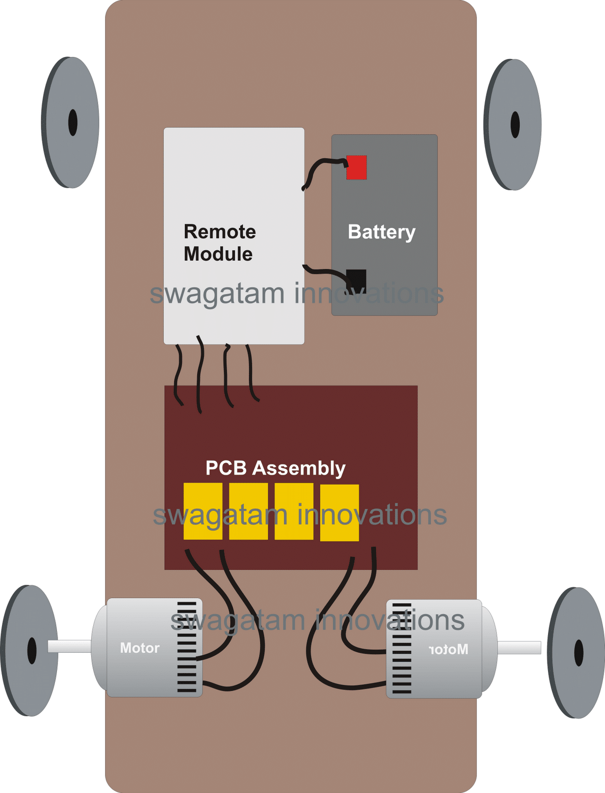
Wheel Set up
You may also want to learn how to make a heavy duty remote controlled trolley circuit for malls and retail shops
After this, the PCB may be populated and wired up with the relays and the diodes with the help of the given figure, this concludes the relay box assembly.
Relay Wiring Details
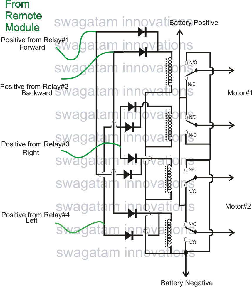
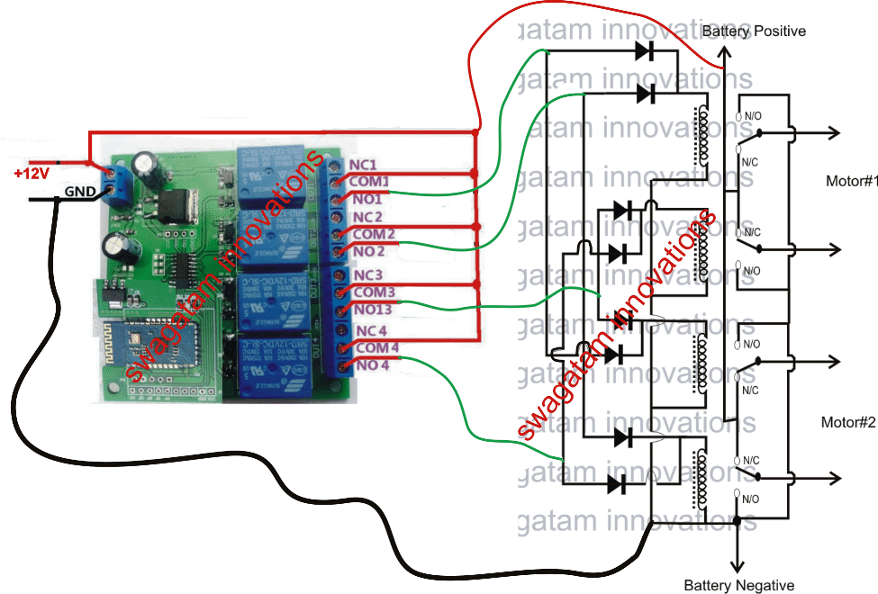
Next, the four relay outputs from the remote control in-built relays should be connected to the diodes of the above relay box circuit.
The antenna from the remote should be sufficiently terminated using a foot long flexible wire so that the module becomes responsive even from longer distances.
The operation will need battery power, so needless to say a suitable battery will also be required to be placed and integrated with the discussed circuits inside the toy car.
Done!. Now you may test the unit by pressing the remote handset buttons.
As per the integration of the relay serial numbers to the diodes of the relay box, pressing of the buttons A,B,C, and D over the remote handset would produce results in some specific orders, such as: forward, reverse, right and left movements with the car.
The entire PCB along with the remote control module may be suitably enclosed over the base of the model car such that the system gives an appearance of a well groomed homemade remote controlled car.
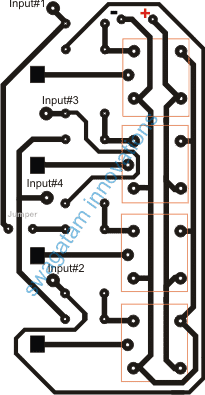
PCB Layout for the Remote Controlled Car (Track Side)




Questions & Answers
refer to this article, you will have to procure the shown remote control unit from your local market:
https://www.homemade-circuits.com/2012/08/how-to-buy-and-use-rf-remote-control.html
hii…jus suggest any website,wer can i learn about all this stuff(diodes,relays,transmitters,recievers etc etc),i knw how to make wired rc car bt i knw nthg about wireless plz…..suggest mee..anna
I personally do not know any such appropriate website, there are many that will provide you with circuits, but there arn't any proper tutorial sites
hello sir,
can i use any remote,which mean's my old remote control cars remote?
can i………………….?
if it has 4 relay outputs, then yes you can use it with the above circuit.
the relays you are talking about in this module can make car very heavy which can make car move slow can you recomend any light weighted transistors to use. can you provide us any circuit for wireless webacam so we can make a spy car.
thanz in advance.
relays are actually very light, so no problem, yes webcam can be added by installing ready made wireless cameras in the car.
can you provide us wireless webcam circuit? I already have Logiteck 720 pixels 500ma webcam i want a circuit so i can attach it to my RC car.
Thanz in advance.
You can easily buy them online, see these examples:
recordcctv.com/images/mini_camera.gif
Hi please can i see the circuit diagram for the remote control
remote control circuit can be seen here:
https://www.homemade-circuits.com/2012/02/how-to-make-remote-control-circuit-from.html
…..sorry here's the correct link:
https://www.homemade-circuits.com/2013/07/simple-100-meter-rf-module-remote.html
And also i need the circuit diagram of a wireless camera thanks in advance
Hi sir can I use xbox 360 controller for it
No, it won't work
And what is the function of relay 4
hi, i am Ramesh from chennai,i want make wireless remote car,so any one can help me,what are the things need and how much cost it will take to complete..? please help me its very urgent ,,
contact : r.ram2012@gmail.com
Hi, I have explained the design in the above article, you can try it out.
Hi,i decided to do the home made wireless remote car business so pls who can do the wireless remote car pls contact me
email : r.ram2012@gmail.com
good morning sir
em new student
sir as u represented in figure there is remote module n
in component there is no one
can u tell me about remote module it which is to use or
or what this helical part is a relay ?
please make me clear.
yes, those are the relay coils.
HOW MANY MATERIALS IS NEEDED FOR MAKING THIS R.C CAR
Boss can u plz give me a circuit which on/off relay by getting sound of alarm .
I'll try to produce it soon in my blog!
Boss plz give me a circuit wich can on/off relay by geting the alarm sound than start forever relay on.
please check out the design here:
https://www.homemade-circuits.com/2014/05/sound-activated-remote-control-circuit.html
Where can I get these simple circuit kit. I want to teach my 8th standard son.
Mumbai Lamington Road
Sir
Please solve out my problem I have 40 MHz Rc car but it can't move forward it only move backward I have checked all components of transmitter and circuit but nothing to get anything
If your Rx incorporates relays, listen whether it clicks or not for both the modes…or connect two LEDs across the motor with opposite polarity and check if the LEDs light up alternately in the forward backward modes…. each of the LEds must have individual 1k resistors in series….
Hello Swagatam i m having remote control car n i want to make its remote so how i can make it..
Hello vaibhav, that can be difficult, unless you know the frequency of operation of the car Rx module
Sir how to turn this rc car left or right . what mechanism to use w.r.t relay connections to move left and right movements of tyres ??
Jayesh, the left/right function are executed using the assigned keys in the remote handset…the "left" button actuates the relay#4 while the right button actuates the relay#3….. the action stops one of the motors momentarily which in turns causes the car to take either left or the right turn.
please sir how i make a toy car with a remote control,please list the required implement for me.
I have explained it in the above article, please read it carefully, the basic method will be the same for your application also
hi can i have a clew of a remote car.
i need the picture of the remote control
i want to make a toy car with remote control but how do i go about it.
i need a toy car inplements.
Hello. I wanted to turn on and off 2 dc motors using ir remote. I designed the ckt but used bd139 instead of relay. But the does not work. But removing transistor it works. Please provide the correct transistor with proper base resistor
If the motor total current is less than 4 amps
you can use a TIP122
use 1 K for the base
make sure to use a heatsink for the transistor
Sir, anyway I tested with bc548 to trigger a relay. That relay should switch dc motor. But the problem is when I press ir remote the state of 4017 o/p doesnt changes, it works fine when the relay driver stage is removed. I followed the exact ckt available in net.
that can never happen unless something is wrongly connected.
connect an LED in series with the transistor base resistor…..and see whether it toggles or not in response to your Tx activation
Please I need a smart remote control circuit for an inverter using a smart phone. Thanks
you can try this
https://www.homemade-circuits.com/gsm-car-ignition-and-central-lock-using/
sir i need a circuit related to h bridge which have pwm pin and also feasable for 12 to 24 voltages and upto 10 amp current .i need it for robo war .will it be possible?
Muhammad,
you can try the first circuit explained in the following article:
https://www.homemade-circuits.com/h-bridge-mains-voltage-stabilizer/
since you would be using 12V, you cam eliminate the 33K resistor and the zener, but for 24V make sure to use a 7812 regulator for the IC