I have posted many battery charger circuits in this site, some are easy to build but less efficient, while some are too sophisticated involving complex construction steps. The one posted here is possibly the easiset with its concept and also is extremely easy to build. In fact if you had all the required material you would build it within 15 minutes of time.
Introduction
The concept is indeed hugely simple and therefore pretty crude with its going. This means that though this idea is too simple, would require appropriate monitoring of the charging conditions of the battery, so that it does not get over charged or damaged.
Materials Required
To make this simplest battery charger circuit quickly, you would require the following bill of materials:
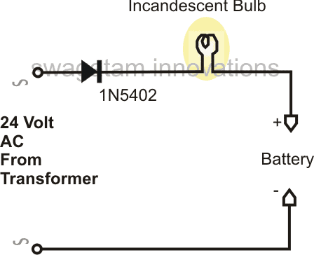
- One rectifier diode, 1N5402
- An incandescent bulb, having voltage rating equal to the battery which needs to be charged and current rating close to 1/10th of the battery AH.
- A transformer having voltage rating equal to twice that of the battery voltage and current twice the charging rate of the battery. That means if the battery is 12V, the transformer should be 24V, and if the AH of the battery is 7.5 then dividing this by 10 gives 750mA which becomes the recommended charging rate of the battery, multiplying this by 2 gives 1.5Amps, so this becomes the required current rating of the transformer.
Building this Simplest Charger Circuit
After you have collected all the above material, you may simply connect the above parameters together with the help of the diagram.
The functioning of the circuit may be explained in the following manner:
When the power is switched ON, the 1N5402 diode rectifies the 24V DC to produce half wave 24V DC at the output.
Though the RMS value of this voltage may appear to be 12V, the peak voltage is still 24V, therefore it cannot be applied directly to the battery.
To blunt of this peak value, we introduce a bulb in series with the circuit. The bulb absorbs the high peak values of the voltage and provides a relatively controlled output to the battery, which becomes self regulatory through the glow of the filament intensity of the bulb (varying resistance).
The voltage and current thus automatically becomes adjusted to appropriate charging levels which becomes just suitable for the battery safe charging.
The charging of the battery can be witnessed by the gradual dimming of the bulb as the threshold charging voltage of the battery is reached.
However once the battery voltage reaches close to 14.5V, the charging must be stopped, irrespective of the bulb glow condition.
Circuit Diagram
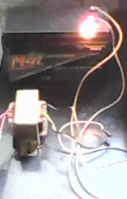
Video Clip showing the charging process using a single diode:


Questions & Answers
Hi sir I want to use 24v dc smps supply to charge 12v car battery 50 AH through 12v bulb in series can I use resister instead bulb
What would be ratting of resister.
Hi Fayyaz, Resistor will not work, you will need a filament bulb only, because in a filament bulb the filament illumination adjusts the current automatically as per the battery charging status.
Thanks for reply
Sir can I use LM 317. 5 or 10 in parallel to obtain 14 v. Or lm 317 with mosfet
Yes you can use many LM317 IC or LM338 ICs in parallel to increase current. Just make sure to mount them over a single common heatsink and mount them very close to each other on the heatsink
Can you tell me if there’s a way to build a charger for a sealed led acid battery. Its cycle use is 7.20-7.5v
And stand by use 6.75-6.9v
1.35A max
You can try one of the designs explained in the link below, just make sure to replace the 5V input with 8V Dc input:
https://www.homemade-circuits.com/usb-automatic-li-ion-battery-charger/
Good morning . I have recently been given a ” PARSONS 4 IN 1 MULTI TOOLL ” I don’t know how old it is or can I find any details of it , the previous owner tried to repair the charger then gave up on it , I want to know how to remake a charging circuit board for it the charger adapter is a AD-0514-BS1 with input 240v 50Hz 3W, Output is DC5.3v 140mA , the number of the circuit board is 600924D .
Thank you for any information you may give me . Jim Naughton
Sorry, Unfortunately we don’t have sufficient information about the gadget you have specified, so it is difficult for us to create a charger unit for it. However, you can try replicating the charger through an LM317 based circuit which is quite easy to build.
I am more than delighted to receive a reply so quickly , I am no electronic wizz but I am going to give it a try , cant wait . Thank you very much . Jim Naughton
It’s my pleasure. All the best to you. Let me know if you any more questions.
How do you fabricate a battery charger, using local material, Give the circuit diagram , how to connect the battery charger and the battery.
good day sir
i have a question can i use the yellow cable 12v inside power pack to charger 75ah battery and how may hours it will take it to charger it
Hello abba, without knowing the specifications of your 75 ah charger power pack, it will be difficult for me to provide any suggestions!
Yes, love this place Terrific article
Thank you very much, glad you liked it
I am experimenting with trafo based charger, please what is the effect of putting a capacitor in series with the positive line going to the battery
Pleases explain the whole schematic for proper understanding
I have an ac adaptor input:120VAC 60Hz 31.2W output:12VDC 2A class 2 transformer. i put some aligator clips on it and checked the polarity with a multimeter. is this possible to use on my 12v car battery?
Do you mean for charging? No, 12V cannot be used for 12V charging…you will need 14V
Please what value of resistor and wattage can I use to resist Ac voltage(220v) abit to reduce the DC supply( from 14v- 13.5v) of trafo based charger.
You can use a rectifier diode in series to drop 0.6V
OK Sir, thanks. One diode does not actually drop ,0.7v, please how many diode will I need in series for the drop
To drop from 14V to 13.5V, one diode will be enough.
Hello,
Is it easy enough to create a circuit that charges a 144v 6.5ah nimh battery?
.7A and 166/177V seems to be well suited.
I’d like to charge a hybrid battery in my car that is below detectable voltage range.
Hello, Yes it is quite easy, just make sure the input current is controlled at 600 mA
Good day sir, please I saw a battery charger set at constant value of 27.6v for 24v system, will the battery be fully charged at this level, and is there need for auto cut off. Thanks Swagatam.
Thanks sir, can 1 use 16.5v transformer based charger to charge 12v battery, and cut off at 14.2v, is it safe for the battery.
Adeyemi, it is safe if the cut off is at 14.2V
Thanks so much Chief Swagatam. I used the charger with 16.5v output but immediately it is put on the battery at 12.1v it jumps to 15.5v, so how will I set a cut off @ 14.2v within secs of charging. So what is your advice.
Adeyemi, did you use 10% Ah current for the input supply. If yes then your battery may be faulty.
Adeyemi, for 12V the full charge level is 14.2V, so for 24V it should be 28.4V, so at 27.6V the battery will be only 60% charged, no aut cut off will be required, and it’s fine to use it, although with compromised back up
Greetings Swagatam!
Thank you for hosting this wonderful round-table forum!
I have an older cordless vac where I just recently replaced all of the sub-c batteries that were failing (one group of 6 and another of group of 2). It charged fine a good 20-uses during a couple of weeks of renewed use, then just failed to charge a week ago.
Unfortunately, I was not aware that the charging AC adapter (12v 300mah) had also failed and was putting out 21v instead of ~12v. I think it might have burnt-out a component or three, as the PCB is noticeably darkened around at least one component (a diode I think). I do not know when this damage occurred, or when the AC adapter actually failed.
I just replaced the AC adapter with a new one (12v that tested at 11.5v, don’t know how to test 300mah, but it was rated as such) and the batteries are still not charging even after a good overnight charging session.
There is a small PCB with the on/off switch with a diode and two other components including an LED indicator (not lighting-up either), but no other major/large components like an inverter or transformer. There is also a circuit pack with some components that I cannot identify that is enclosed in a clear thick sealed plastic bag between the batteries and the aforementioned PCB.
I’m hoping you can assist me in troubleshooting this issue.
Thank you DAMatson,
If you are trying to charge a 12V battery then you will have to supply around 14V to it to initiate the charging and charge the battery to 70% level.
So you must go for a 14V adapter, or you can simply get this by using a bridge rectifier and a 1000uF/25V capacitor with a 0-12V transformer, this will give you a roughly 16V, which you can apply directly across the battery. The slight over voltage will not affect the battery if the transformer current is rated at 10 to 15 times lower than the battery Ah.
Sorry, I neglected to mention that the Batteries are 1.2v Sub-C, in series (6 in one group, 2 in another), so that would be 7.2v total in the first group, and 2.4v in the second group.
The original A/C adapter was 12V (300mah), so that is what I ordered as a replacement. It worked fine for 10 years, so I was presuming that since it was measuring 21v that it had merely gone bad.
OK, I guess the only way the two groups could possibly be connected is in series, making the total voltage 9.6V, and that’s why a 12V adapter is used. In that case you can use a 12V 300mA adapter for charging the cells.
yes 21V is dangerous and could ruin the battery very quickly…it might have already caused a lot of damage to the cells.
I went ahead and pulled the batteries apart and checked each one and only one was damaged. This was the first thing that I did two weeks ago. The overnight charge was the next logical step, but when that failed, that’s when I reached-out to you.
I’m suspecting that one of the components in the PCB has been burnt-out, or maybe one of the components in the sealed clear plastic “bag”.
I’d be happy to send you pics via e-mail of these two items so you can more easily identify the components involved.
Hi David, I have replied you in the email, here’s what I said:
From the pictures it seems nothing is burned, the burnt look on the PCB could be due to the heat generated by the center resistor which appears to be a 15 ohm resistor.
This resistor could be the current limiting resistor, and in the process could be getting very hot and causing the baking of the PCB.
You can probably check the values with a multimeter for confirmation.
Hi, am a students from Nigeria I have a 15v transformer, how can I charge my 3 12v 7ah batteries.
Thanks.
Hi Shams,
use a bridge rectifier with filter capacitor and stabilize the output with a 7812 IC.
use 4 nos of diodes in series with the ground pin of the 7812 along with a 2K2 resistor as done in the following article
https://www.homemade-circuits.com/2012/11/high-current-transistor-tip36-datasheet.html
ignore the TIP36 stage, and the 1 ohm/10 ohm resistors those are not required for your application…
I am a beginner here and I tried making a battery charger using a transformer from a computer UPS rated 800VA..but when i try to charge a 12v lead acid battery, its ammeter reading exceeds to my 30A ammeter..can i lower this current when charging battery or is it ok to charge battery with high current? thanks in advance for your answers..
you did not mention the voltage rating from the trafo, and the battery AH rating??
make sure the voltage is as per the specs of the battery, otherwise you may quickly damage you battery with a mismatched input
for limiting current you can add a 24V truck head lamp in series or use the following concept, if your batt AH is within 50AH range
https://www.homemade-circuits.com/2013/06/universal-high-watt-led-current-limiter.html
don't forget to replace LM117 with LM338
connecting a 12V battery with 220V will be disastrous!
Dear instructor, my name is Otunba Richard Olaniyi-Oshin from Nigeria. I'm a Mathematician but I am in love with constructing simple appliances that could solve modern day problems. I have been searching for a simple battery charger that could charge my 12volts 200amps batteries because my inverter didn't come with an inbuilt battery charger; thanks for the simple diagram above. I have read that all I need are 12v transformer, diode and battery terminal clips. Sir, my question is, how do I connect the diode to the transformer? Is it to any of the 2 wires of the 12v transformer. Pls, enlighten me. Thanks for solving our problems! God bless you.
Dear Richard,
the above charger will charge your battery but it will not switch OFF after the battery has reached full charge, therefore you may have to monitor it with a voltmeter, and switch it OFF once charged fully.
the diode can be connected to wire, it's not critical…..but the transformer will need to be rated at 20 amp 15V minimum
Thanks Danang, I am glad it worked for you as proposed in the article.
but instead of using parallel 1N4007 diodes, you must use a single 1N5408..or put 1 ohm 1watt resistors in series with each of the 1N4007 diodes
will try to publish it soon…thanks
I tried use LM 317 T, but failed 🙁
What LM 317 and LM 317 T are different?
please do it as shown in this diagram:
https://www.homemade-circuits.com/2012/02/how-to-make-current-controlled-12-volt.html
LM317 T should also work
Sir, I have adapter 19V 3,5A, how to step down Voltage to 14V and Current to 1A?
you can use an LM317 voltage regulator circuit for implementing it.
I have a UPS that doesn't work anymore.
But there is a transformer inside it.
And I have a car battery too, 25Ah.
I have another UPS that works well but is not enough to charge this battery.
How can I use the working UPS and the battery with the components of the older UPS to get an inverter kind of thing?
you can look for the parts inside the bad UPS that's indicated in the second diagram of the following link, and use them to make the shown automatic battery charger circuit
https://www.homemade-circuits.com/2011/12/how-to-make-simple-low-battery-voltage.html
Which transformer rating is used if i want to make 12V, 180Ah Battery Charger?
sorry 24V /25 amp
12V….25 amp
hello sir can i charge 4v 2.5Ah sla battery with mobile phone charger??
yes you can do it
Sir the output voltage is just 10.2v
Can I still use it
you have used a bridge, or a single diode???
I mean 12×2 v 1.5amps transformer
use center tap and one of the outer taps, connect these with a bridge network, filter the bridge output with a 2200uF/25V cap and connect it with your battery, wait for 10 hours.
Pardon sir.
I have a 3 anodes 12v, 1.5amps, how can I use it to charge a 12v, 7.2ah battery?
How long will it take for full charge
what's 3 anodes?? please clarify
Thanks sir.
Can i use 12v 500milliamp transformer to charge the battery
with a 12V/500ma, use a bridge rectifier, a 2200uF/25V filter cap and simply connect the output directly to the battery, wait for 15 hours and you'll find the battery reasonably charged.
Welldone sir,
I want to make this but i have some question.
1. Can i use this circuit to charge an sla battery 12v, 7.2ah?
2. Is the circuit safe for charging battery? And how long will it take to charge d above battery fully?
3. Can the output be fully rectified and filtered for pure dc?
4. What adjustment can be made to give more quality ? Thanks
sorry it's not back up time, it should be charging time in the above comment….
…back up time is 10 hours with a 1amp trafo for a 7ah battery
thanks Madamidola,
the circuit is safe but crude so will need to be switched off as soon as the 14.4V mark is reached.
yes the given specs are for charging a 12V battery
if you intend to rectify the the transformer output with a bridge network, do not use a 24V trafo, rather use a 12V trafo and a12V automotive bulb
for more quality, you may include an opamp based cut-off satge, use lm338 stage for regulation, use heat sensors etc.
Sir.. Can i use another diode if i have not that one? And what diode can i use?
John, you can get it from any 3amp/5amp power supply box or a power amplifier circuit etc.
you can also try making it by putting two or three 1N4007 diodes in parallel.
Sir.. Where can i find rectifier diode 1N5402. Can i find that in an old appliances?
how can i make a battery charger?with the help of this b.c.how can i charge different types of battery like cellphones battery or cars battery?can it possible?
this circuit cannot be used for charging all types of batteries, for cel phone batteries you will need more complex designed as already explaimed in many of the posts in this blog
Dear Sir,
How to read this design. Is it like the current first comes to transformer then diode then bulb and then battery? Can I use this same way to charge a battery through power produced by mini wind turbine?
Thank you,
Rahul
Dear Rahul,
yes you can read it in that way.
With a wind generator you would need a voltage regulator circuit also because the supply from a wind generator could vary a lot.
Hello Gopal,
Presently I do not have a multi-charger circuit for 180AH battery, I'll try to design it if possible, and let you know.
Hello sir,
I ant to design a charger which can charge batteries at 10 times of rated current, for quick charging…
pls suggest some info about it.
Hello Pooran,
It will damage and destroy the battery, so it's not recommended.
connect the 4V source directly with your phone battery (3.7V) and remove it as soon as the phone battery reaches 4V.
the source current supply must not be more than the cell phone battery AH rating.
no, this circuit is not applicable for small batteries.
Thanks sir,
Will ur above circuit is able to desulphate batteries
Can i use 12-0-12 trafo by connecting 12-12 tap together
hello avijeet,
for the above circuit you will need only one diode as shown and you can connect 12-12 tap for getting 24V.
yes a 25amp diode bridge can be used for 150ah battery charging.
hello sir,
can u please teach me how to use 12-0-12 transformer to get 0-24 for above circuit.
will i have to connect 12-12 tap directly for 24
or via diodes
->can a bridge "D25SBA80" should be used as bridge rectifire in a 150ah battery charging circuit.as it is rated to handle 25 amp current according to its datasheet.(not related to above circuit)
Thanks sir
yes you can do it.
And can i use 12-12 tap together to get 24v from 12-0-12 trafo
I am not sure, but since it generates pulsed DC at 50Hz can be tried for the purpose.
Thanks for ur reply sir,
Will u give me some idea of components i had to use for 12v 9.4ah amp battery. actually i want to desulphate this baterry.
And how would i know that my battery is charged
Thanks
If you are referring to the above circuit then you may try a 24V/5amp transformer and a 12V automotive headlamp.
Keep an ammeter connected in series with the supply, it should indicate gradual increase in the current consumption, and subsequently a gradual decrease in consumption, until zero.
Hello Sir,
What type of battery charger u r discussing with mr carl carbeau in above discussion.
I had also read some where to make battery charger by simple ac run capacitor and by diode bridge.is it fisiable and safe to charge high ah rating battery with this charger.i had also read that it also helps in desulphating the battery as u where also discussed above.
Yes it can be done, but the whole wiring becomes risky and the terminals of the battery float at the mains potential, the whole thing becomes very dangerous to touch.