In this post I have explained a simple yet effective low battery cut-off with indicator circuit which can be integrated with cell phone/tablet charger battery packs in order to monitor and avoid battery draining below a set threshold. The idea was requested by Mr. David.
Technical Specifications
Hi Swagatam.
I know it was asked before, but still, if you can help me out, I'd really appreciate it. I'd like a circuit/ic for purely low voltage cut off. I have a 8-pack of AA (NiMH LSD) batteries, which should never discharge below 7.2V. I'm using these with a (car) 12V to 5V USB charger, which I'd like to use on the go.
The setup of simply using a transistor and a variable resistor in conjunction with a TIP122 transistor for handling larger currents, resulted in draining the battery further than the absolute minimum of 7.2V. I'd like this to use this with no relays (as they use too much power). I'm looking at 0.5-1.5A on the primary side (batteries) and 1-2.5A on the secondary 5V side.
For charging both the phone and the tablet. I just hate it, when a circuit like this is used in a 1$ devices. I don't want to buy of the shelf products.
Thank you really much! -David
The Design
The circuit functioning of the proposed cell phone/tablet low battery indicator with cut off can be understood as follows:
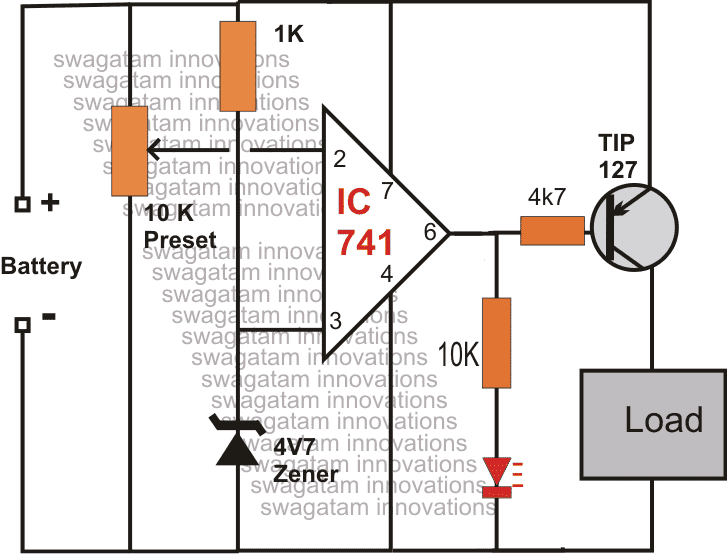
Assuming the connected battery pack to be fully charged, the potential at pin#2 is allowed to be at a higher level than at pin#3 by setting the 10k preset appropriately.
The above condition ensures a zero or logic low at the output pin#6 of the IC.
The above low output enables the connected transistor TIP127 to conduct and charge the cell phone or the tablet at its collector.
As the battery pack drains below the mentioned 7.2V mark, pin#2 voltage becomes lower than pin#3 which instantly makes the output of the IC high, switching off the transistor and the load.
The situation is indicated by the red LED which just lights up due to the low battery conditions.
At the above threshold, the output might oscillate for some time due to battery voltage trying to restore at the previous mark as soon as the load cuts off.
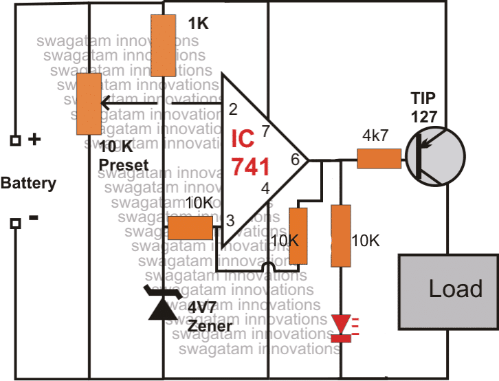
Although not necessary, the above outcome can be avoided by adding a resistor network: one across pin#3 and zener cathode, and another across pin#6 and pin#3, the values can be anywhere between 10K and 100K.
Circuit Diagram
How to Set up the Circuit:
It's simple, apply the desired low voltage threshold to the circuit and adjust the preset until the LED just illuminates brightly.
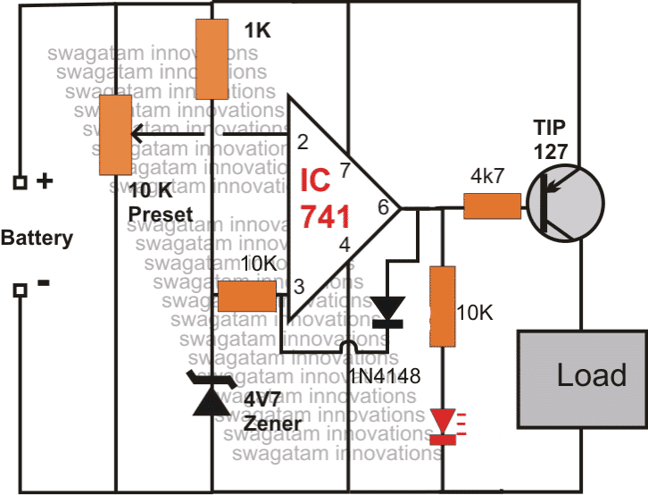
As mentioned earlier, the possible oscillation at the thresholds can be prevented by adding some hysteresis to the above design, it may be done by the following two methods, the second option appears to be more logical and clean.
While setting the preset, make sure the feedback link stays (pin6 to pin3) disconnected, you can connect it back once the preset adjustment is complete.
Note: Please add a 3V zener diode in series with pin#6 of the opamp, (anode to pin#6), in order to counter the off-set voltage problem.


Comments
Hi Sir, I have made a mini ups for Router and Onu Unforthunetly while electricity go after a long time of backup battery got low voltage. to avoid that I want to make a Under voltage auto load cutt off circuit. My battery is 18650 Model Laptop old battery which operate 3.3-4.7v . I want to cutt off the circuit while battery come into 3.5v Dear Sir Please help me.
Hi Jobayer, you can try the first circuit from the following article. Replace T1 with TIP32, T2 with BC547, R1 with 1k, and the zener can be a 3.3V.
https://www.homemade-circuits.com/battery-deep-discharge-protection-circuit/
Dear Sir I made this and working fine without load. when load connected circuit is not working. Could you please help me to solve this issue. or what to do ?
Hi Jobayer,
Which circuit did you try from the following article? And also please explain how did you exactly test the following suggested circuit, with load and without load? I will try to help…
https://www.homemade-circuits.com/battery-deep-discharge-protection-circuit/
you can implement it through an opamp based battery charger circuit, as shown in the second or the third diagram from the following article:
https://www.homemade-circuits.com/2011/12/how-to-make-simple-low-battery-voltage.html
Capacitor solved it. Seems to work now and maybe you need to update your circuit image with 1K resistor, 3v zenerdiode and capacitor 🙂 thank you for your support Swagatam!
I am glad that worked for you Robert, if time permits I will surely correct the diagram accordingly.
I tried to disconnect it completely. Turn up the voltage on power supply by 1v above asjustment and then connect the circuit back to power. It is still cutted off and led is lighting. Only thing thats resets it is when I connect it back and disconnect diode between 6 and 3 and connect it back. Would really like it to work the way you describes it.
I also connected a 3v zener in series vid resistor and base and that works aswell
connect any small value capacitor across positive rail and pin#2 of the IC and now check the response of the LED by switching OFF power
Turning it off will surely reset it, try disconnecting the clips from the board and you will find the circuit returning to the original position, however adjusting the voltage will not change the condition while the diode connected and the upper limit triggered.
the above condition is not related to leakage current, it's the earlier issue of the relay not switching OFF which was due to the leakage, you can also connect a white LED in series with the transistor which will give you a clear idea regarding the transistor switching
Thank you swagatam!
But how do you reset it. What I can remember it was the same even if I turn it off and on again with raised voltage.
Is it possible it leaks any small current anywhere? Maybe better to go with zenerdiode than 1K over base and emitter?
I tested with 1K resistor and it seems to work. I get 0v when LED turns on. Circuit is only working correct when the diode 1N4148 is disconnected. If I connect this diode and turn up or down input voltage, circuit will not go back when voltage gets over my adjustment. The LED will be on regardless of what I do. But when diode is disconnected circuit will work as expected. I also have som loss in output voltage compared to what i put in.
OK that's fine,
the diode is introduced exactly for that, it's for locking the IC into a switch OFF condition as soon as the battery full charge level is detected, otherwise the output will keep fluctuating ON/OFF as the battery charges, drops, charges at the threshold rapidly.
you can remove the diode if you don't want the latching feature…
I connected a 10kohm resistor and then things start to happen. If i measure in parallell i get 1.1v and if I measure with diode disconnected I get 0.6v. If I try with LED light of and passing current through I only get 11.6v out when I have 12v in
It could be due to leakage voltage from pin#6 of the opamp which is not allowing the transistor to switch OFF….connect a 1K resistor across the base and emitter of the TIP127, or you can also try a 3V zener in series with the base of the transistor, the anode will go towards the base and the cathode towards the resistor.
Hi, assembled everything but it does not seem to work. I disconnect
1n4148 diode between pin6 and pin3. Connect 12v voltage and trim to LED lights up. Then connect the diode between pin6 and pin3 again, but I always got 12v out on load,it doesnt matter what I do I get 12v out everytime and it does not cut off .I thought it would cut off when led is on. What can I have done wrong?
s32.postimg.org/4mp5na2lx/image.jpg
s32.postimg.org/dg3nla08l/image.jpg
Thank you!
Just got components but confused how to place Tip147?
This is what i bought:
TIP147 TO-218 PNP 100V 10A
Hope I got the correct one 🙂
yes that's correct, you can easily find the pin config from the datasheet of the device
depending on the resistor value between pin6 and pin3, the power will be reconnected to the battery at some lower threshold of the battery voltage.
And how does turn on again work?
Sorry for all the questions
Hi,
Can I use this with a 4cell lithium battery pack?
Do I need any modification?
Want it to cut voltage at 14v. How many amps can it handle? My load is using approx 3-5 amps. Thanks!
Should I replace the 1k resistor or 10k resistor from pin 3 with 100k resistor?
yes it can be done to minimize consumption
…sorry, it's the 1K resistor which can be replaced with a 100K
Hi, you can use the above designs for your requirement…no modification is recommended for the mentioned 14V low batt cut-off.
the amp rating depends on the transistor spec…you will need to replace the TIP127 with a TIP147 for handling 5 amps
Thank you very much for your fast answer.
will the circuit oscillate? Im using Panasonic NCR 18650 B batteries.
no, it will not oscillate due to the presence of the feedback resistor/diode.
Thank you Swagatam!
Had some problems finding IC741 at my local shop. Is this the same
LM741CN dip8 single op-amp?
And can I use any 10K trimpot?
Is this circut efficient? Is it going to take much power from the battery?
Appreciate your help!
You are welcome Robert
yes a 741 will come as an 8 pin IC just like the 555 IC
any 10K trimpot will work at the indicated position.
you can increase the efficiency by increasing the 10k trimpot to 100K trimpot and the zener resistor also to 100K, this will restrict the IC consumption to not more than 5mA max in the standby position.
Which one is the zener resistor?
Thx!
Sound very good!
But is the circuit consumption 5ma after cut off? Is it not possible to drain battery over time even on smaller load?
yes it will be around 5mA once the battery is cut off
Should i parrallel the zener to 1N4148 ..
NO, the pin6 voltage must pass through the zener before reaching the associated external components.
it must be between pin6 and the rest of the associated components.
Thanks for your response sir..
Can u give me a file of this circuit done in CIRCUIT WIZARD in computer. . ,because i want to do your ckt in pcb
ive done it last night in circuit wizard . But the load(output voltage) doesn't totally cut off ? ….. @8V The led lights and the output voltage is maximun(8V) and @7 wich is the cutt off stage must be .the led still lights… And the output voltage is partial decrease to 1/2 of inital.
AND @6V THE led is off and the n0 output voltage..
is this correct sir?? Or theres wrong.
What i expect is at 8V The led is off the load is on. @ 7V (cutt off stage .) the led must be on and load must totally off.
waiting for ur response sir. I gonna buy the c0mponents tommorow.
Romeo, I am sorry it won't be possible for me at the moment due to my busy schedule.
the issue could be due to leakage voltage (offset) at the opamp output.
try adding a 3V zener between pin6 and the other associated components.
anode will be toward pin6
Thanks sir.. So i must totally rem0ve the 4.7 zener diode in the circuit and dont replace it with any c0mponent.? Right sir?
then i'm just wondering how could I set the low voltage limit to cut off the load of this circuit. .can u give me a detail procedure sir? .
Thanks again sir.
Romeo, I was referring to the 1N4148 diode, not the 4.7V zener.
the low voltage limit is set by adjusting the 10k preset
Sir can i use this circuit . As autocut off for 8V batt pack
what i suggest is if the voltage reach 6.8V(ADJUSTABLE) the transistor turn off and the red led will light … And when the voltage raised even at just 7V or the transistor must turn on again…
Hoping that you can make a circuit for me ..
and send it to me via
romeojr.gasilan@gmail.com
waiting for your response sir.
Romeo, you can use the above design for your application, just remove the the feedback diode so that the circuit can function according the mentioned 0.2V deviation
sir kya me is circuit ko 6v/4.5 bettry pr use kar sakta hu.sir mujhe led driver ko 4.1-4.2 volt pr cutt off karwana he.or bettry low indicate karna.he.kya me is circuit ko.o/p ke pehle laga kr cutt off nd low indicate kr sakta hu.plzz sir help me
yes, you can use the above circuit for your mentioned application.
sir kya me is circuit ko 6v/4.5 bettry pr use kar sakta hu
yes you can use the above circuit with a 6V battery
Test setup:
AU 1.00$ Car USB charger ( http://www.ebay.com/itm/251324420472 )
Samsung Galaxy S (Screen ON – max brightness, at IDLE)
Voltage adjusted with LM317 from a (solar) battery, 12V 65Ah
1.2m custom USB cable for charging only, about 0.3mm2 each of the two wires
At 7V, the phone slowly discharges
at 7.5V, the phone does charge quite quickly
The results are good, because I will not discharge the pack to 7.2V. I did this once and one (AA NiMH) battery reached a dangerous 0.3V. I will see how many times I can charge the phone with a full 8-pack of AA's discharged to 7.5 or 8V. To be on the safe side (of the batteries).
I dont know how did you think I would use the LM317. I am using the LM317 for nothing but in a testing environment. I was testing your circuits with it, because that is the only adjustable power I have. I am seeing now, that electronics will remain as a hobby. Thank you for the help you gave me and everyone else. And the LM317 is not a solution. It is a linear regulator, which is *perfect* for batteries. I ordered a boost circuit from ~3V to 5V 1A for $1. This will solve my problem once it arrives. I used more gas when I went to get those parts in my motorbike than that thing costs. I learned a little bit about opamp.
Bye for now 🙂
Hi Swagatam, as I just had a minor motorbike accident, it will give me plenty of time to figure this circuit out as I have to rest.
When I had connected the charger to the LM317 who acts as a voltage regulator, I noticed the output was always 5.2V under no load and when the input was around 6V. I will test and confirm as you suggested with the phone attached and charging.Also, I will try connecting a 5mm 3.5V white LED in series as you said. For the hysterisis, I have a 1MR potentiometer which I plan on using and later buying a fixed resistor.
Rough explanation:
The circuit is set to cut off at 7.2V without the 1N4148 diode or resistor from pin #3 and pin #6.
I am just unsure as to why the hysterisis works as in (I insert the diode);
-the voltage drops to 7.2V
-T1 stops conducting
-voltage is raised to ~10.7V
-T1 does not conduct, which is okay, but then
-input power ("from the battery") is cut off
-input power is reconnected at 10.7V
-T1 still does not want to conduct.
I would like to do this because I have many battery packs and I would just replace the depleted one with a full one.
I will write back, once I have some results.
Many thanks…
Hi David,
That's exactly why we have inserted the diode, for latching the circuit so that once the voltage drops to 7.2V, the output becomes high permanently, and stops the transistor from conducting, even if the voltage climbs to higher levels.
Here it's climbing to 10V because the transistor has switched off the load, and with no load the voltage becomes free to climb to the desired higher level.
Hi Swagatam!
I am sorry to say, but I am slowly but surely giving up on this circuit. The transistor switches ON and OFF perfectly, I can adjust the switching by 0.01V. The hysterisis is the part that makes me want to give up. Just today I spent three hours different things, from zener diodes, diodes, resistors, potentiometers, nothing seems to work. The closest that I got was a few days ago with the 33k resistor. I applied 10V, T1 switches ON, I lower the voltage to 7.2V, T1 switches OFF, I raise the voltage to 10V again, T1 remains switches OFF. T1 just does not conduct enough to charge my phone(0.5A-1A), yet alone my tablet(1A-2A). I even could not set the hysterisis with the diode from pin #6 to pin #3. If I raise and lower the voltage output remains HIGH. But if I rotate the potentiometer set to pin #2, output goes LOW (~1.6-1.9V) and high (input voltage).
I do not mind experimenting, if you have any ideas. I bought 5 of each items required to assemble this circuit. I can blow a few, but so far, I have not managed to. I have tried to use a different LM741, but AFAIK, the chips all worked. If the input on pin #3 is higher than pin #2, the output is HIGH. I have even used the 4v7 zener diode, so the LED connected to output would not be dim, when the output is LOW.
I will greatly appreciate any additional explanations or ideas.
Thank you for your time!
Hi David,
Just a few words, before I give the explanations: Please remember that electronics works on well defined principles, it will not obey unless the principles are grasped and implemented correctly.
The above message is for all in this blog who try different circuits and fail to make them work.
Coming back to the circuit, if you recall, we added the feedback resistor/diode for latching the circuit once the battery level dropped below 7.2V mark, latching means it will not respond even if the voltage is increased, we did this to stop the circuit from oscillating at the particular threshold.
This feed back link is called the hysteresis; here we have set this hysteresis point to such a level where it almost has to reach the 12V mark for resetting.
Now supposing you wanted to cancel the latching feature, and have a variable hysteresis feature wherein the circuit could be restored say when the voltage reached to 9V or 10V, in that case the diode will need to be removed and replaced with a 100K or 220K or 500K preset (whatever suits best), this would allow you to set the restoration point as desired. Then you could get the circuit to switch ON back at 8V, 8.1V…….12V, as you wished.
The second point here is the current required for charging the phone….my question is if the battery pack was joined directly to the phone and its voltage varied from 7V to 12V, does the phone keep charging under these varying conditions?
Please do confirm this practically.
If suppose the phone accepts the charge right from 7 to 12V when connected directly, then we can go ahead and check why the transistor isn’t allowing this to happen.
The TIP127 can supply upto 2 amps and its base 4K7 resistor is correctly calculated to provide this much current, so according to me it should charge the battery.
For indication and for preventing parasitic voltage from reaching the transistor base, I would recommend the LED to be connected in series with the base of the transistor; this would provide you with clear indications with regard to the transistor switching.
Please consider the above points and see how things work out, there’s absolutely no way this circuit would fail:)