• Skip to main content
  • Skip to primary sidebar

Homemade Circuit Projects

Need circuit help? Post them in the comments! I've answered over 50,000!

Blog | Categories | About | Contact | Calculators-online
You are here: Home / Datasheets and Components / LM311 Datasheet, Circuit Applications

Circuit Simulator: Assemble and Simulate

LM311 Datasheet, Circuit Applications

Last Updated on April 17, 2023 by Swagatam 2 Comments

The LM311 is a versatile, fast voltage comparator with multiple capabilities. Its output stage is "open collector" and "open emitter," allowing for various configurations. It can directly control relays and its output can be compatible with several logics, including TTL.

Table of Contents
  • Technical Specifications and Datasheet
  • Description:
  • Maximum characteristics:
  • Operation:

Technical Specifications and Datasheet

Here are some of the technical specifications of the LM311 comparator IC:

  1. Type: Voltage comparator
  2. Pin Configuration: 8-pin DIP (Dual In-line Package)
  3. Output Type: Open-collector and open-emitter
  4. Input Voltage Range: -0.3 V to Vcc - 1.5 V
  5. Response Time: 200 ns typical, 1.2 µs maximum
  6. Power Supply Voltage Range: Single supply: 5 V to 30 V, Dual supply: ±15 V
  7. Input Bias Current: 250 nA typical, 500 nA maximum
  8. Input Offset Current: 20 nA typical, 200 nA maximum
  9. Input Offset Voltage: 2 mV typical, 7 mV maximum
  10. Maximum Output Current: 50 mA
  11. Maximum Input Voltage: ±30 V
  12. Temperature Range: -25°C to +85°C
  13. Package Type: 8-pin DIP, 8-pin SOIC (Small Outline Integrated Circuit)

Description:

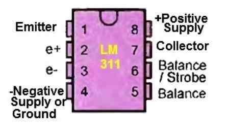
Figure 1 below shows the pinout of the LM311 in a DIPS package. This comparator is designed to operate with a single supply voltage between 5 and 30 volts or with a symmetrical supply between +/- 15 volts.

LM311 pinouts

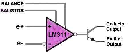
Its output stage is buffered by a power transistor, as shown in Figure 2 below, which presents an internal structure schematic of the LM311.

LM311 internal structure

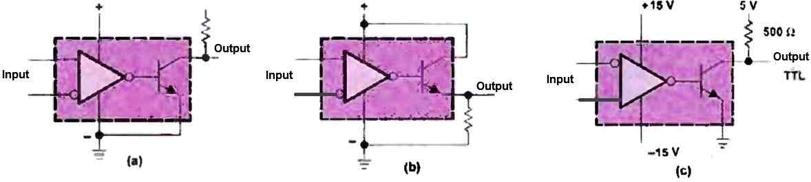
This feature allows for various configurations of this comparator, as shown in Figure 3 below. The LM311 can command DTL, RTL, TTL, and MOS logic circuits indiscriminately.

LM311 input output and supply configurations

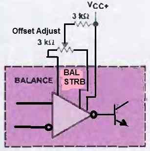
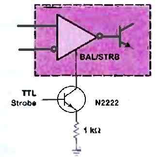
Its open collector output allows for obtaining a wired logical OR. Additionally, the LM311 has an offset adjustment (Figure 4 below) and a strobe function, which forces the output to the high state (next Figure 5).

LM311 offset adjustment
LM311 strobe feature

If pins 5 and 6 are not used, they must be connected together.

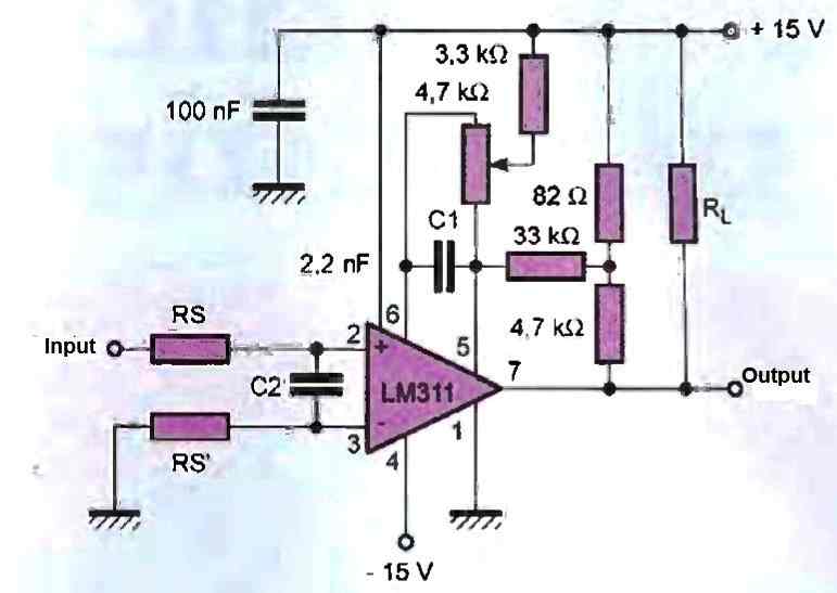
The stability of the LM311 with certain sources, such as a very slow change in voltage, is achieved by placing a capacitor on the differential input of the comparator.

This capacitor, C2, will have a capacitance between 100 pF and 1 nF and will be directly connected to both inputs (Figure 6 below).

application circuit for LM311

Thanks to its output transistor, a load of up to 50 mA under 50 V can be controlled, which is another advantage often exploited. Therefore, the LM311 is capable of controlling relays, lights, and small motors.

Maximum characteristics:

The maximum voltages of the LM311 are 36 V for the supply between pins 4 and 8, and +/- 30 V for the differential input voltage between pins 2 and 3.

The maximum voltage difference between the output and the negative supply, i.e., between pins 7 and 4, is 40 V, and 30 V between the emitter output and the negative supply, i.e., between pins 1 and 4.

Additionally, the output can withstand a momentary short-circuit for up to 10 seconds.

Operation:

Consider the LM311 comparator circuit shown in the last Figure 6 above, powered by a symmetrical voltage.

If (e+) < (e-), then Vs = 0 V, the load RL is powered, and the voltage across its terminals is Vcc minus a voltage drop due to the saturation voltage of the output transistor and the current through the emitter resistance of 4 S2, which is internal to the LM311.

If (e+) > (e-), then the output transistor of the LM311 is blocked, and no current flows through RL. The load is therefore not powered.

You'll also like:

  • 1.  Alarm Signal Generator IC ZSD100 Datasheet, Application
  • 2.  TSOP1738 Infrared Sensor IC Datasheet, Pinout, Working
  • 3.  LM324 Quick Datasheet and Application Circuits
  • 4.  IC LM358 Datasheet and Specifications
  • 5.  Ferrite Core Material Selection Guide for SMPS
  • 6.  IC 4011 Datasheet, Pinout, Applications

Filed Under: Datasheets and Components Tagged With: Applications, Datasheet, LM311

About Swagatam

I am an electronics engineer and doing practical hands-on work from more than 15 years now. Building real circuits, testing them and also making PCB layouts by myself. I really love doing all these things like inventing something new, designing electronics and also helping other people like hobby guys who want to make their own cool circuits at home.

And that is the main reason why I started this website homemade-circuits.com, to share different types of circuit ideas..

If you are having any kind of doubt or question related to circuits then just write down your question in the comment box below, I am like always checking, so I guarantee I will reply you for sure!

Previous Post: « Proximity Detector using Hall Effect Sensor Circuit
Next Post: Delay OFF Lamp Timer Circuit »

Reader Interactions

Comments

  1. Ali says

    September 30, 2024 at 3:50 pm

    Hello I would like to make a monostable timer circuit using an lm311 what can I suggest about this

    Reply
    • Swagatam says

      September 30, 2024 at 5:45 pm

      Hello Ali, I can certainly provide you with the required circuit diagram, but before that can you please tell me why you want to use the LM311 IC and not any other comparator or opamp IC, because a monostable can be built using any opamp or even with a single MOSFET?

      Reply

Need Help? Please Leave a Comment! We value your input—Kindly keep it relevant to the above topic! Cancel reply

Your email address will not be published. Required fields are marked *

Primary Sidebar


Subscribe to New Posts

Categories

  • Arduino Projects (89)
  • Audio and Amplifier Projects (132)
  • Automation Projects (17)
  • Automobile Electronics (101)
  • Battery Charger Circuits (83)
  • Datasheets and Components (104)
  • Electronics Theory (143)
  • Free Energy (37)
  • Games and Sports Projects (11)
  • Grid and 3-Phase (19)
  • Health related Projects (25)
  • Home Electrical Circuits (12)
  • Indicator Circuits (14)
  • Inverter Circuits (88)
  • Lamps and Lights (142)
  • Meters and Testers (69)
  • Mini Projects (46)
  • Motor Controller (64)
  • Oscillator Circuits (27)
  • Pets and Pests (15)
  • Power Supply Circuits (108)
  • Remote Control Circuits (50)
  • Security and Alarm (64)
  • Sensors and Detectors (101)
  • Solar Controller Circuits (59)
  • Temperature Controllers (42)
  • Timer and Delay Relay (49)
  • Transmitter Circuits (29)
  • Voltage Control and Protection (39)
  • Water Controller (36)

Tags

AC Alarm Amplifier Application Arduino Automatic Battery Charger Circuits Control Controlled Controller Current Datasheet DC Detector Digital Driver Electronic Explained Explored Generator High Indicator Inverter Lamp LED Light Meter Motor Power Regulator Remote Sensor Simple Single Solar Supply Switch Timer Transistor Voltage Water Watt Working


Other Links

  • Privacy Policy
  • Cookie Policy
  • Disclaimer
  • Copyright
  • Videos
  • Sitemap


People also Search

555 Circuits | 741 Circuits | LM324 Circuits | LM338 Circuits | 4017 Circuits | Ultrasonic Projects | SMPS Projects | Christmas Projects | MOSFETs | Radio Circuits | Laser Circuits | PIR Projects |

Social Profiles

  • Twitter
  • YouTube
  • Instagram
  • Pinterest
  • My Facebook-Page
  • Quora
  • Stack Exchange
  • Linkedin


  • Recent Comments

    • Swagatam on How to Make HHO Fuel Cell Circuit in Automobiles for better Fuel Efficiency
    • Swagatam on How to Make HHO Fuel Cell Circuit in Automobiles for better Fuel Efficiency
    • eq on How to Make HHO Fuel Cell Circuit in Automobiles for better Fuel Efficiency
    • Swagatam on How to Make HHO Fuel Cell Circuit in Automobiles for better Fuel Efficiency
    • eq on How to Make HHO Fuel Cell Circuit in Automobiles for better Fuel Efficiency

    © 2025 · Swagatam Innovations