The IRFZ44 is a popular N-channel power MOSFET designed for high current applications. Here is a detailed datasheet of the IRFZ44 MOSFET:
General Information:
- Manufacturer: International Rectifier (now part of Infineon Technologies)
- Model: IRFZ44
- Type: N-channel power MOSFET
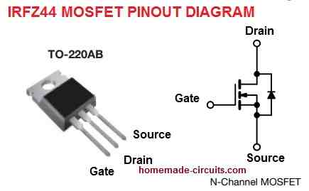
- Package: TO-220AB
Pinout Configuration:
The following shows the pinout configuration for the MOSFET IRFZ44:
Electrical Characteristics:
- Drain-Source Voltage (VDS): 55V
- Continuous Drain Current (ID): 49A @ 25°C, 35A @ 100°C
- Maximum Power Dissipation (PD): 94W @ 25°C
- Gate-Source Voltage (VGS): ±20V
- Drain-Source On-Resistance (RDS(on)): 17.5mΩ @ VGS=10V, ID=27A
- Gate Threshold Voltage (VGS(th)): 2V to 4V
- Input Capacitance (Ciss): 1320pF @ VDS=25V, VGS=0V, f=1MHz
- Output Capacitance (Coss): 310pF @ VDS=25V, VGS=0V, f=1MHz
- Reverse Transfer Capacitance (Crss): 225pF @ VDS=25V, VGS=0V, f=1MHz
- Total Gate Charge (Qg): 47nC @ VGS=10V, ID=27A
- Gate-Source Charge (Qgs): 7nC @ VGS=10V, ID=27A
- Gate-Drain Charge (Qgd): 12nC @ VGS=10V, ID=27A
Thermal Characteristics:
- Thermal Resistance, Junction-to-Ambient (RθJA): 62°C/W
- Thermal Resistance, Junction-to-Case (RθJC): 1.5°C/W
- Operating Junction Temperature Range (TJ): -55°C to 175°C
- Storage Temperature Range (TSTG): -55°C to 175°C
Features:
- Low RDS(on) for high efficiency
- Fast switching speed for improved performance
- High current handling capability
- Low gate drive requirements
- High input impedance
- Avalanche energy rated
- RoHS compliant
Applications:
The MOSFET IRFZ44 is commonly used for the following applications:
- DC-DC converters
- DC to AC 50 Hz, 60 Hz Inverters
- Switching power supplies
- Motor control
- Solenoid and relay drivers
- High frequency inverters
- Class D audio amplifiers
- Electronic ballasts
- Battery chargers
- Welding equipment
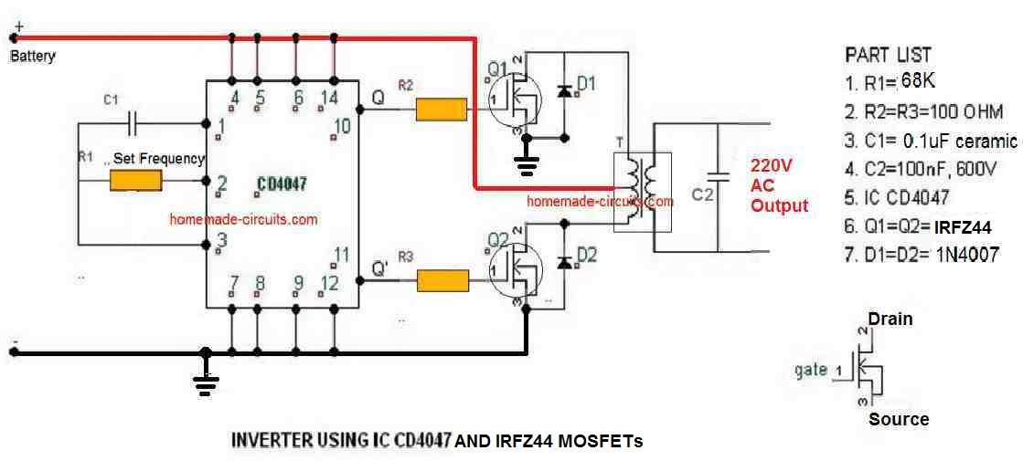
Inverter circuit using IRFZ44
Conclusion
Overall, the IRFZ44 MOSFET is a high-performance, reliable device that can be used in a wide range of applications. Its low RDS(on), fast switching speed, and high current handling capability make it an ideal choice for power electronics applications.


Comments
Thank you very much! I will add the gate diode hopefully that will help my mosfet heating problem.
Sure, no problem!
I have read several places that switching off quickly is much more important than switching on quickly. Do you have any idea why this could be?
Yes that’s correct, that is why we use a BJT driver stage at the gate or a reverse diode across the gate resistor. Quick switch OFF of the gate ensures quick discharge of the internal capacitance of the MOSFET gate and lower heat on the MOSFET.
Nice! Even would the diode would’nt the switch off time be limited by the current sink capability of the SG3525?
Without the diode the current has to pass through the gate resistor which can be slower, with a diode it becomes faster.
Is this diode important with an IGBT as well?
I think yes, since an IGBT also has a gate just like a MOSFET
Hello could I drive this high frequency with a TL494? 30kHz
Yes you can.
Hello, would this mosfet be ok being driven at 33kHz from an SG3525 without a mosfet driver?
Yes, it’s OK, just make sure to incorporate a gate resistor and a diode as indicated in the following diagram:
https://www.homemade-circuits.com/wp-content/uploads/2013/09/howtopreventmosfetfromburning.png
The resistor value can be 10 ohms