Let’s say we have a push-pull or full bridge inverter and its output goes to the primary of a transformer, and the secondary gives you high voltage AC like 220V square wave.
Now to make this AC waveform smooth and more like a sine wave we connect an LC low-pass filter just after this secondary, like this:
Connections Details of the LC Filter:
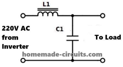
- Take the two output wires from the transformer secondary — this is your 220V AC (square wave).
- Now we connect a series inductor (L) in one of the wires — just one wire, like in series, not both wires.
- Then after the inductor, we put a high voltage capacitor (C) across the output, like between the two wires, that is parallel to the load.
Now to caalculate the values of the L and C, you can use the following calculator:
Inverter Output LC Filter Calculator
How to Decide this fc Value?
We do not want to block 50Hz because that is our main signal. We want to block the switching frequency harmonics like:
- 300Hz
- 600Hz
- 1kHz
- And higher junk frequencies
So we choose fc just above 50Hz but much below the unwanted high frequencies.
Rule of Thumb:
You can select cut-off (fc) between:
3 × main frequency......... upto 10 × main frequencyExample:
If your inverter PWM has big amount of noise like around 1kHz to 3kHz, then you pick fc = 300Hz, so that:
- 50Hz passes cleanly.
- Above 300Hz (like 1kHz, 2kHz) get blocked fast.
- Gives smooth sine output.
Final Tip:
So just take 5 or 6 times the 50Hz, then:
fc ≈ 50 × 6 = 300HzIt is a safe and effective choice for LC filter to clean inverter waveform.
Example Calculations:
Now let me give you a clear manual example calculation using our default values so visitors can verify the tool step-by-step.
Let us assume:
Vrms = 220V
P = 500W
f = 50Hz
fc = 300Hz
STEP 1: Calculate Load Current
I = P / Vrms
I = 500 / 220
I = 2.27 A
So the load current is:
I ≈ 2.27 A
STEP 2: Calculate Inductive Reactance Term
XL = 2 × pi × fc
XL = 2 × 3.1416 × 300
XL = 1884.96
STEP 3: Calculate Inductor Value
Your formula:
L = Vrms / (XL × I)
Substituting:
L = 220 / (1884.96 × 2.27)
First multiply denominator:
1884.96 × 2.27 = 4278.86
Now divide:
L = 220 / 4278.86
L = 0.0514 H
Convert to mH:
L = 0.0514 × 1000
L = 51.4 mH
So,
Suggested Inductor ≈ 51 mH
STEP 4: Calculate Capacitor Using Resonance Formula
Formula used in your code:
C = 1 / ((2 × pi × fc)^2 × L)
First calculate:
2 × pi × 300 = 1884.96
Now square it:
1884.96^2 = 3,553,057
Now multiply with L:
3,553,057 × 0.0514 = 182,694
Now invert:
C = 1 / 182,694
C = 0.00000547 F
Convert to microfarads:
C = 0.00000547 × 1,000,000
C = 5.47 uF
So,
Suggested Capacitor ≈ 5.5 uF
FINAL VERIFIED RESULTS
Load Current ≈ 2.27 A
Inductor ≈ 51 mH
Capacitor ≈ 5.5 uF
Important Practical Note
This is a simplified theoretical LC design. In real inverter systems:
• Inductor current rating must be higher than 2.27 A (preferably 1.5× to 2× margin).
• Capacitor must be AC rated (polypropylene recommended).
• ESR and inductor DCR will slightly shift cutoff.
• Final tuning is usually done experimentally.
Comments
Do you have same formula to calculate it?
Can you send me it by mail?
Tanks. Srecko.
Hi, I have updated the formulas with example calculations in the article above, please check it and let me know…