In this post we will try to analyze a few interesting IC LM338 based power supply circuits and related application circuits which can used by all hobbyists and professional for their day to day electronic circuits and experiments
Introduction
The IC LM338 by TEXAS INSTRUMENTS, is a versatile IC which can be wired in numerous different ways for obtaining high quality power supply circuit configurations.
The following circuit examples simply depict few of the very interesting useful power supply circuits using this IC.
Let's study each circuit diagram in details:
Simple Adjustable Voltage Power Supply Circuit
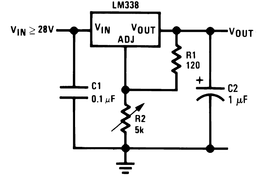
The first circuit shows the typical wiring format done around the IC. The circuit provides an adjustable output right from 1.25V to the maximum applied input voltage which shouldn't be more than 35 vots.
R2 is used for varying the output voltage continuously.
Simple 5 Amp Regulated Power Supply Circuit
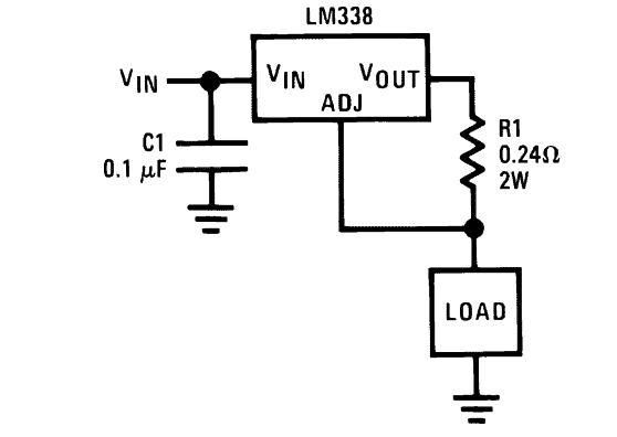
This circuit produces an output that may be equal to the input supply voltage but the current is well regulated and can never exceed the 5 Amp mark. R1 is precisely selected so as to maintain a safe 5 amp maximum current limit that can be withdrawn from the circuit.
15 Amp, Variable Voltage Regulator Circuit
The IC LM 338 alone is specified for handling a maximum of 5 Amp of current, however if the IC is needed to handle higher currents, in the region of 15 amps, it can well be modified to produce that much of current with the appropriate modifications as shown below.
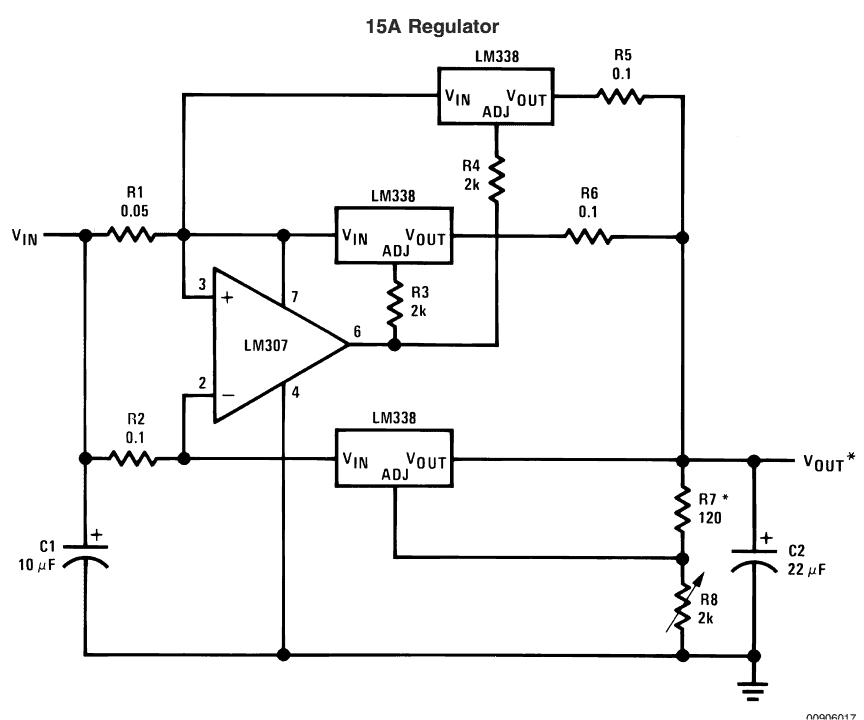
The circuit utilizes three IC LM338 for the intended implementations with output voltage that's adjustable as explained for the first circuit. R8 is used for the voltage adjustment operations.
Digitally Adjustable Power Supply Circuit:
In the above designs, the power supply utilized a pot for implementing the voltage adjustment procedure, the below given design incorporates discrete transistors which can be digitally triggered separately for obtaining the relevant voltage levels at the outputs.
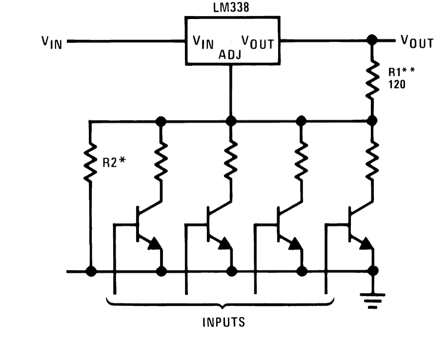
The collector resistance values are chosen in an incremental order so that a correspondingly varying voltages can be selected and becomes available through the external triggers.
Light Controller Circuit
Other than power supplies, LM338 can also be used as a light controller. The circuit shows a very simple design where a phototransistor replaces the resistor which normally acts as the component for adjusting the output voltage.
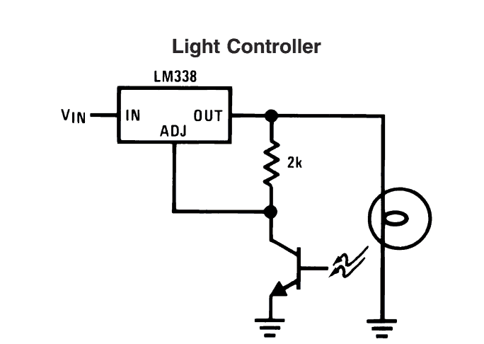
The light which needs to be controlled is powered by the output of the IC and its light is allowed to fall on this phototransistor.
As the light increases the value of the photo-transistor decreases which in turn pulls the ADJ pin of the IC more toward the ground, forcing the output voltage to decrease which also decreases the light illumination, maintaining a constant glow on the lamp.
Current Controlled Power Supply Circuit:
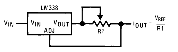
The next circuit shows a super simple wiring with the IC LM338 whose ADJ pin is connected to the output after a current sensing preset. The value of the preset determines the maximum amount of current that becomes permissible through the IC at the output.
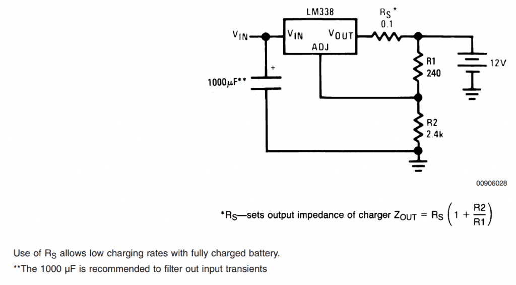
12V Current Controlled Battery Charger Circuit
The circuit below can be used to charge a 12 volt lead acid battery safely. The resistor Rs may be selected appropriately for determining the desired level of current for the connected battery. R2 can be adjusted for obtaining other voltages for charging other categories of batteris.
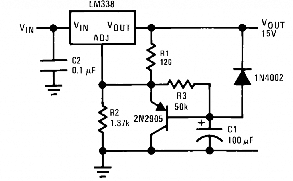
Slow Turn ON Output Power Supply
Some sensitive electronic circuits require a slow start rather than the usual instant start. The inclusion of C1 makes it sure that the output from the circuit rises gradually to the set maximum level ensuring the intended safety to the connected circuit.
Heater Controller Circuit
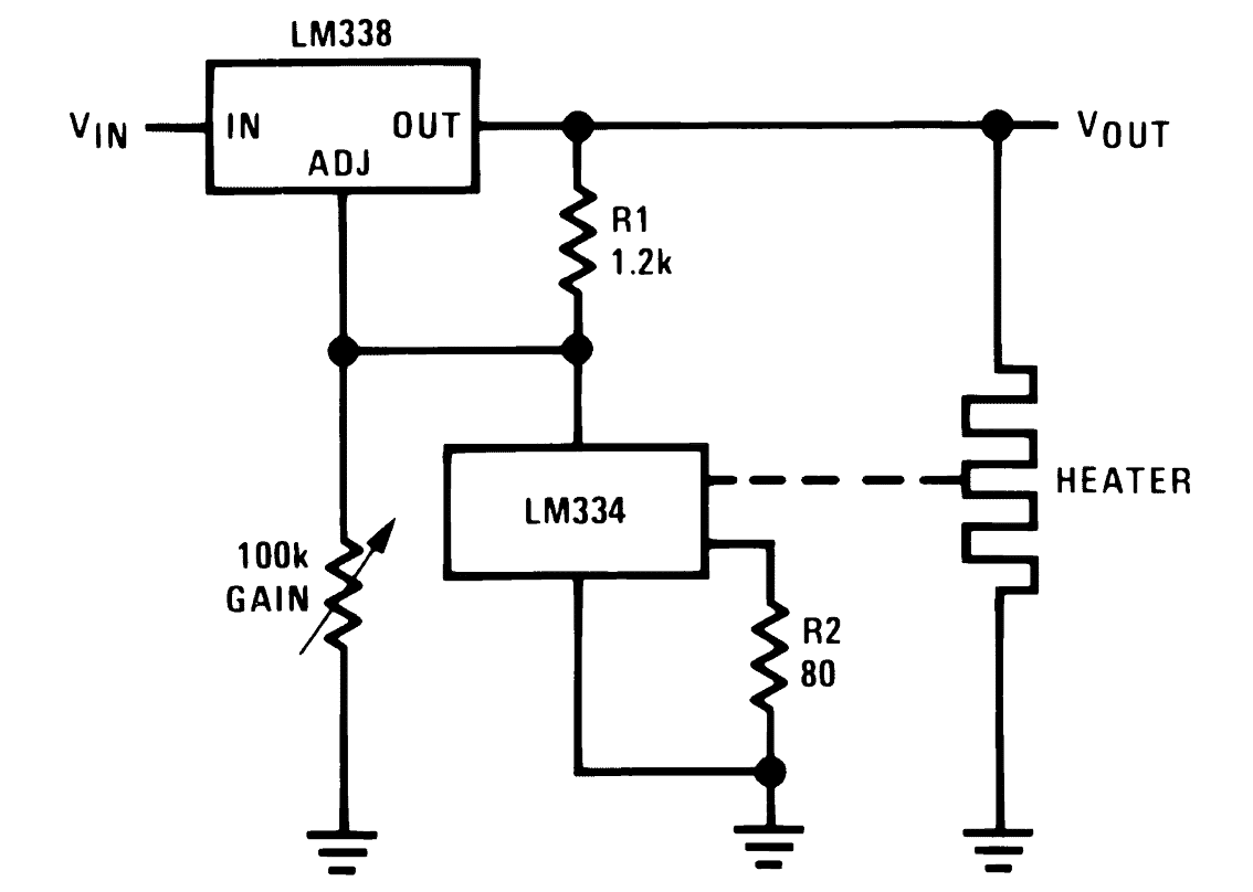
IC LM338 can also be configured for controlling temperature of a certain parameter like a heater. Another important IC LM334 is used as the sensor which is connected across the ADJ and ground of the IC LM338. If the heat from the source tends to increase above the predetermined threshold, the sensor lowers its resistance correspondingly, forcing the output voltage of LM338 to fall, subsequently decreasing the voltage to the heater element.
10 Amp Regulated Power Supply Circuit
The following circuit shows another circuit whose current is restricted to 10 amps, that means the output can be made suitable for high current rated loads, the voltage is adjustable as usual via the pot R2.
Adjusting Many LM338 modules via a Single Control
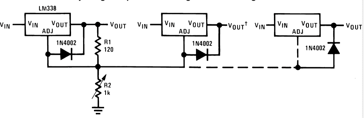
The given circuit shows a simple configuration which can be used for controlling the outputs of many LM338 power supply modules simultaneously though a single pot.
In the above section I have explained a few of the important application circuits using the IC LM338, which were basically collected from the datasheet of the IC, if you have more clues regarding such LM338 based circuits, please let us know through the comments below.


Questions & Answers
good day sir,
regarding the 12V Current Controlled Battery Charger Circuit, can is use rectified DC from a motorcycle as V_in?
if possible, what voltage of the capacitor would you recommend? is it ok to use 1/4w for all resisitors?
thank you.
Regards
Good day Jhunix, yes you can use the motorcycle alternator input after rectification, but it should not exceed 35V.
Use 10uF/50V at the input and 100uF/25V at the output of the IC.
Can i use LM317 or any equivalent IC replacing LM338? because I can't find LM338 in any electronic/electrical store here in or place.
317 will charge only upto 10AH batteries not above that.
sir some times 7805 get short circuits & it gives 12v output how i save my mobile from 12v output
give your reply
prashant, 78XX ICs are internally short circuit protected, they will never get shorted unless tampered intentionally. Even if this happen, the cell phone is protected against upto 12V supplies and will simply show"not charging"
good day sir. i wat to build a powersupply with lm338 but i want to be able to adjust the curent to not just the voltage i saw a schematic above with a simple curent limiting circuit.but if i make that circuit how can i adjust the voltage not just the curent?
good day,
please refer to the first diagram in the following link:
https://www.homemade-circuits.com/2012/11/3-watt-5-watt-led-dc-to-dc-constant.html
Replace the transistor with a Darlington pair (two BC547) and replace the base resistor with a 10k pot. The slider arm will go to ground while the two ends across base and 0.6 ohm resistor.
this pot can be used for setting the current limits.
hello sir
how to find R1 values(ohms,watts) for current controlled power supply . i am using 12v 80ah battery and need output current : 3.5 amp to drive led array of 30 * 1 watt leds
hello aashish, please go through the following article, it has all the required info in it:
https://www.homemade-circuits.com/2013/06/universal-high-watt-led-current-limiter.html
thank you
i hav read that article and got the formula R1 = Vref/current,
1.25/3.5A=0.357 ohms ,4.375watts is it correct
that's correct.
good morning swagatam
regarding 12V Current Controlled Battery Charger Circuit
I have 12v 35Ah battery, 0-12v 5A transformer. Charging current required must be around 3.5A.
Is ther anything i should modify about
Rs .1 ohm
R1 250 ohm
R2 2k7 ohm
Hi Phoenix, If you have calculated them correctly nothing more needs to be done in the circuit…that's all is needed.
is Rs .1 ohm appropriate for a 35 Ah battery. I didnt calculate this value. I took it from the image above.
0.6/3.5 = 0.17 ohms is the approximate value
i want to charge 12v 4.5ah battery form 17v 11 watt solar panel is the value Rs=0.1 is correct for the arrangement ?
I am not quite sure about it, I think the following circuit would be more suitable for you:
https://www.homemade-circuits.com/2012/02/how-to-make-current-controlled-12-volt.html
sir but my input is 17vdc from a solar panel…the link you have provided is for 220ac supply…
Hello sir, I'd like to know how to charge a 12V7Ah lead gel-acid battery, I know that the "slow charge" must me 700mA, so I have to supply the battery with 700mA, and I don't know how to calculate the external components. Thank you very much for the help beforehand
hello Jeronimo, you can build the first circuit from the above article exactly as shown, just replace the pot with a 10k pot…. for setting up the circuit adjust the pot to get around 14V at the output without any battery connected. once this setting is done connect the battery and switch ON power…let it charge for about 8 hours and then you could switch OFF the supply manually, you would find the battery fully charged by this time.
LM317 may be used instead of LM338 to make the circuit cost effective…
Ok, thank you very much
For the 5amp power regulator you have a resistor set for 2W and .24ohms
If we use I^2*R=(25amp)*(.24ohm)=6W, So wouldn't the resistor need to be a minimum of 6W?
by using the more general VxI formula and by considering the fixed reference voltage across the resistor = 1.25V, we get P = 1.25 x 5 = 6.25 watts
yes, you are right, the datasheet's calculation is incorrect, the resistor should be rated at above 6 watts and not 2 watt
Hello sir, i want to build a 5A 12v battery charger, what value should i use for Rs, R1,R2 and what is the resistor watt preferable? Thank you
Hello Hardy, you can keep Rs and R1 as shown in the diagram, R2 can be replaced with a 10k pot and this pot could be adjusted to set 14.3V at the output, for the recommended 12V/5A battery charging
Thank you very much sir
Sir I want to make a mobile charger out of it can u pls help me by the spec if I want the output as 5v 1.5amp and it should be stable . the input is taken from a bike battery which is about 12v
Ashraf, you can try the following linked circuit:
https://www.homemade-circuits.com/2012/04/how-to-make-solar-battery-charger.html
adjust P1 to get precise 5V at the output and use it for your purpose, also calculate R3 appropriately for limiting current to the desired limit.
HI SWAGATAM JI
PLEASE HELP ME I HAVE REQUIRED A 24 VOLT 5 AMP CHARGING CIRCUIT FROM TRANSFORMER POWER SUPPLY WITH PROVISION OF PARALLEL LOAD 1.5A ,AUTO TURN ON BATTERY IN THE ABSENCE OF SUPPLY POWER
Hi Gajendra ji, you can try the last circuit from this article…
https://www.homemade-circuits.com/2011/12/how-to-make-simple-low-battery-voltage.html
Hey sir.. Smit here
Sir i m trying to make battery charger and for that I have used lm317 but using this circuit I can charge mobiles upto certain mAh. If I connect mobile which is having higher mAh than mobile is not charging.so give me solution how can I make it useful for all mobiles.
In my circuit I have used lm317 and and one 10k potentiometer is connected with its adjustable leg and than other all of potentiometer is connected to 180 ohm resistor. Out terminal of lm 317 is connected with that resistor and one more resistor of value 4.7 ohm. And than I have connected one zener diode of 6.2v, 0.5 W,, after that I connect one diode 1 N4007. And this diode is connected to female USB connector help me pls..
Hi Smit,
a good LM317 would be capable of generating in excess of 1amp which should be sufficient for most cellphones.
I think the 4.7 ohm could be causing some significant drop in current…. try reducing its value and see the response…and also make sure the LM317 is mounted over a large heatsink and adequately cooled.
yes it will work, the resistor value would be
1.25/1 = 1.25 ohms 1/4 watt
for more info you can refer to the following article
https://www.homemade-circuits.com/2013/06/universal-high-watt-led-current-limiter.html
Hi Swagatam,
Say we have a pc smps that supplies 15A at 12v rail,would lm338 current regulator work if a 10W LED requires 12v and I want to drive it at 700mA.Can current be fixed to 700mA using LM338 current regulator?
If it can be used then R value would be R=(1.25/0.7A)=0.87ohm.Right?
Whats the power dissipated by resistor and power rating of resistor should be used?
Following the above can we cascade the above leds in parallel,say 7 (i.e 700mA x7=4.9A),
so the ckt should pass on 4.9A to the led array.
Hence R required would be R=1.25/4.9A=0.25 ohm.Am I right?What should be the power rating required by the resistor in that case?
And if I want to work on above 5A,can LM 196 be used in similar fashion?
Sorry for asking too many question,Just want to learn and experiment 🙂
Hi Abhishek,
you can try the following design for achieving any desired current control
https://www.homemade-circuits.com/2011/12/make-hundred-watt-led-floodlight.html
yes your calculations are correct.
the power rating of the resistor would be
1.25 x 4.9 = 6.1 watts.
LM196 can be replaced directly with LM338 for getting 10 amp control
Hi. I built the 15A voltage regulator circuit using LM338 (3) and LM307. This was connected to my power supply (home made from computer power supply). I also connected a 3 wire V/A meter.
Everything seems fine when switched on, but there is no power output.
What should I look for to find the fault?
Hi, without knowing about the schematic it can be difficult to understand what exactly you have made, and regarding a possible fault in the design.
Please what replacement for lm307, it is not available in my area, thanks.
you can use opamp in that place. If you decide to use IC 741 make sure to add an offset null adjustment to it.
Thanks sir, what value of preset is appropriate to use in the 741ic with added null adjustment
Tolu, please search for “741 null offset” and you will be able to find all the required details
I have 6 32 AH 12 VDC batteries in my 200 watt Solar array.
I have set the charge voltage to 13.7 VDC
But the amps is more than a LM338 can handle. it also passes through a 3 wire Volt/Apere meter 0-100VDC and 0-50 Amp which is via a shunt in the Negitive line.
Can I put a transitor or MOsfet accross the LM338 of around 25 Amperes to increase the current.
If so can you recomend types and circuit mods
yes that’s definitely possible, you could probably try the concepts explained in the following articles:
https://www.homemade-circuits.com/lm317-with-outboard-current-boost/
https://www.homemade-circuits.com/how-to-make-solar-inverter-circuit/
If I want to make 2.5 Amp Regulated Power Supply Circuit, then I have to change the 0.24 ohm resistor to 0.5 ohm. But I want the input voltage is 26V, is it possible?
Yes you can use 0.24V for getting 2.5 amp limit, it will work for the entire voltage range
Do You mean 0.24 ohm?
OK. What is the maximum input voltage? Is It 40V?
Yes, 0.24 ohm, I mistakenly wrote 0.24 V. 35 V is the max input
I have tried to give 26v for input voltage. but, voltage reference doesn’t 1.24V, it becomes around 15V and the output current is more than 3 amp (I’m using 0.5 ohm to get 2.5 amp). I’m sure that my circuit is right, so what are the problems?
Please check the voltage across the resistor, is it 0.6V? if not increase its value a bit more…
No, it is not 0.6V. It is more than 15V. I dont know why. If the input voltage is 4V, the voltage across the resistor is already 0.6V, when I give bigger input voltage then the voltage across the resistor is bigger too. It seems impossible to reach 26V input voltage and has 2.6 Amp on the output.
Or you can suggest me, how to build a constant current source with 26V input voltage and 2.6 Amp output?
That is strange, because anything above 0.6V across base/emitter of the BC547 will cause the BC547 to conduct and ground the ADJ pin of the IC which will in turn shut off the output.
Alternatively you can try the following options for getting a constant current output
https://www.homemade-circuits.com/universal-high-watt-led-current-limiter/
Halo sir
May i ask why is the 10AMP regulated power supply limited maximum output of 20v can it go higher?
Hello Joshua, you can increase it by replacing the pot with a 4k7 pot
Halo sir
Thank you for the quick response , let me try to apply the circuit .
Please can you send me your email so as i can send you images of my finished product and let me know your thoughts .
Thanks Joshua, you can send it through your google drive or microsoft drive links, I’ll be happy to post them in the above article.
https://drive.google.com/drive/folders/1ld_qS1tknmIZyV5fzX9Dszrm1FupRiAw
please change to sharing mode so that i can access the link
Sorry for the inconvenience pls try again the link below
https://drive.google.com/drive/folders/1ld_qS1tknmIZyV5fzX9Dszrm1FupRiAw
That looks cool, but which circuit did you exactly build? because the 10 amp design explained in the above article does not seem to have so many parts.
Halo sir
The design has multiple sub circuits but the main circuit is lm338 circuit which has 2 variable resistors to adjust the voltage level, there is the Dual power supply which gives 5v and -5v to power the voltmeter which uses CL7107 ic there is also the sub circuit which provided 5v 1A to with short circuit protection ( it lights red led and buzzer beeps when short is present)which can be used to test digital circuit
Thanks Joshua, for the clarification!
How is the project finishing ,cable running and case design … what should I improve ??
All look good to me!
Halo sir please help!
https://drive.google.com/file/d/1L10NtgJ9LOPnGvGniEpiIQdeHHpxaNCO/view?usp=drivesdkI
Joshua, I can help only if you provide the complete schematic of your design…and also tell about the issue that you are facing
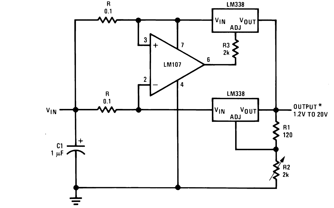
And also whats the use of the 0.1 ohm resistors ? Is it a must to use them if so what how much wattage should i use ?and can i use any opam instead of the lm107 if not available ?
It can be 0.2 x max voltage. If the max voltage is 30V then the result will be 6 watts and so forth.
It helps to keep the dissipation uniform across the two ICs, a simpler idea can be to remove the op amp the 0.1 resistors entirely and put the upper IC in parallel with the lower one, and mount both over a single common heatsink
What is the value of R2 if the output Voltage is 17 ,15 ,13 ,9 ,22 ?
you can try this software
https://www.homemade-circuits.com/lm317-lm338-lm396-calculator-software/
Hi, I am a retired Electronic Engineer but like all engineers we find it hard to give up tinkering, i do enjoy
looking at your circuits, and i am building your simple ajustable power supply circuit to power my new project
Hi, that’s great, wish you all the best with this simple power supply project!
Hello Swagat
I want to use LM338. Constant current 10A for 12V battery 100AH C10.
What is the minimum input voltage required to supply 10Amp current?
thank you
Hello JK, you cannot get 10 amps from LM338. You can get 5 amps max, but even at 5 amps the IC can get extremely hot, and might need a large heatsink.
you could piggyback 2 lm338 ‘s to allow 10 amps surely?
Hello Swagatam
for LM338 in constant current mode 10Amp for 12V bat ; if the input voltage is less than required minimum voltage ; then what will happen? Will it continue with less current or stop fully?
thanks
Hello JK, 12V battery will require minimum 14 V output from LM338, and the input must be at least 3V higher, that is 17V minimum. However, LM338 cannot be used to provide 10 amp current.
Why are there 0.1 ohm resistors at the inputs?,these are not load resistors as you would expect on the output side,are they just for impedance matching and what wattage would they be?
thanks
The 0.1 ohm ensures both the LM338 conduct uniformly, and none of them are able to conduct current more than the other. Wattage = R x I^2 = 0.1 x 5×5 = 2.5.
Thanks for your prompt reply.I am making a temp solar power charger for 12v batteries, before I buy an mppt controller for this 320w panel I am testing this ti 10 amp circuit and most circuits use a forward diode on the input
To prevent any back current,would this not be better?
You can use a diode at the input side to prevent an accidental polarity reversal of the solar panel.
thx swagatam
can you please direct me to a simple temperature regulator? preferably 12v or so and drives a relay
thanks
Here’s a circuit which you can try: It has a relay which operates in response to temperature variations.
https://www.homemade-circuits.com/simple-thermostat-circuit-using/
Hi Engr
In the heater control circuit, i can’t find Lm334, any replacement ic i can use to work with the Lm338 regulator?
Thanks alot for your effort.
Hi Abba,
I cannot seem to find any direct replacement for the LM334. You can perhaps use an LM35 IC with a transistor to replicate the same function.
Dear Sir
I want to make a circuit with the function of controlling the output voltage (0-30V) and output current (1mA-2.5A). I use 2 IC LM338. The first IC is for voltage regulation and the second IC is for current regulation. I use BC547 to protect the IC LM338. I have the schematic diagram and would like to ask you to check if it really works.
Thank you very much!
here is my schematic link
https://www.homemade-circuits.com/wp-content/uploads/2024/09/LM338-with-voltage-and-current-control.jpg
Hi Long, your circuit looks OK to me, however, if you are using an additional LM338 for the current regulation then the BC547 stage is not required.
The LM338 already has an internal over current protection, above 5 amps.
Swagatam
i want to design a four wheel led lamp with switching LEDs i had used total 8 LEDs 2S2P*2 in which it should be operate at 12V DC but the thing is i want to operate it with switching function so it can changes the colour temperature i used the 4 LEDs are of 3000K and 4 LEDs are of 6500K
so can you guide me on it ?
Thanks in advance
Waiting for your reply
Thanks Brijesh,
Do you want the bulbs to be switching alternately and continuously?
Please let me know this then I will provide you with the required circuit design.