ATmega microcontrollers, they are coming from the AVR family which Atmel developed long back, and later this Atmel company was taken by Microchip. So now officially Microchip owns it but still people say Atmel AVR only.
These MCUs became very popular slowly because they are easy to understand, quite affordable, stable in long run and also documentation is very clear.
So hobby people, students, and also professionals all use it together.
The most known one is ATmega328P because Arduino Uno employs this IC in it.
However apart from that there are many more like ATmega8, ATmega16, ATmega32, ATmega128, ATmega2560, and all these are still used everywhere in real projects.
In this article we go step by step, first we see basic things, then hardware connections, programming tools, fuse bits also, and finally we see real C code using AVR-GCC.
The idea is that after finishing this full article, you should feel confident that you can take any ATmega MCU and program it yourself without depending on Arduino library or shortcut methods.
Why people often prefer Atmega directly without Arduino
Yes we know Arduino itself uses Atmega MCU and is very easy to program and implement, so we like it when we start, that is good.
However, when we want full control, efficiency, small size, people skip Arduino and use Atmega directly. Now let us explain why.
First, we save space, Arduino board is big, has voltage regulator, USB chip, crystal, pins all over. If we need small gadget, then Arduino is waste, but Atmega alone fits in tiny PCB, then we solder only what we need making the device compact.
Second, we save cost, Arduino board costs more. Atmega IC plus few parts is cheaper. That is important when we make many devices, then we cut production cost.
Third, we get full register control. Arduino functions like digitalWrite, analogRead, here delay are easy but slow, because behind scenes Arduino does lot of stuff. But Atmega directly allows fast operations, we toggle PORTB or timers directly then code runs faster, real-time control better.
Fourth, custom peripherals, Arduino sets timers, PWM, UART, ADC in default way. But when we use Atmega directly, then we can configure every timer, prescaler, interrupt exactly how we want. So we can make advanced projects like precise PWM, high-speed ADC reading, low-power sleep modes, battery saving, that Arduino often hides or complicates.
Fifth, power consumption!! Arduino always has extra regulator and USB, so it consumes more current. But Atmega alone can run at 1 MHz with 1.8V and almost nothing, then very low power for battery projects.
Sixth, learning, when we use Arduino only, we do not see registers, interrupts, bit manipulation, clock setup, ADC, timers deeply. However using Atmega directly teaches embedded programming deeply, then we understand hardware fully, and we can design professional embedded systems.
So you see bro, Arduino is like training wheels, good to start, but when we want small, fast, cheap, custom, low-power, and fully controlled project, then we move to Atmega directly. Then we feel real power of MCU, that is why people often prefer Atmega without Arduino.
Understanding ATmega Microcontroller Basics
An ATmega MCU is basically like a full small computer inside one IC. Inside it there is CPU, Flash memory where program stays, SRAM where variables live, EEPROM for storing data permanently, GPIO pins for input output, timers, ADC, UART, SPI, I2C which is also called TWI, and also interrupt system is there. So almost everything is inside one chip.
Normally ATmega MCUs come with these common features, not all exact same but mostly similar.
- It is 8-bit AVR RISC CPU
- Clock speed can go up to 20 MHz
- Flash memory size changes from 8 KB to 256 KB depending on model
- Many digital input output pins are available
- Timers and counters are there
- Analog to digital converter is built-in
- Serial communication interfaces are present
- Low power sleep modes also supported
Common ATmega Variants
- ATmega8 is usually used for small projects and basic applications where not much memory or peripherals are needed.
- ATmega16 or ATmega32 are good for medium level projects where more IO and memory is needed.
- ATmega328P is mostly used in Arduino based projects and learning projects.
- ATmega128 or ATmega2560 are used for big projects where many peripherals and large memory is required.
Pin Diagram and Pin Functions
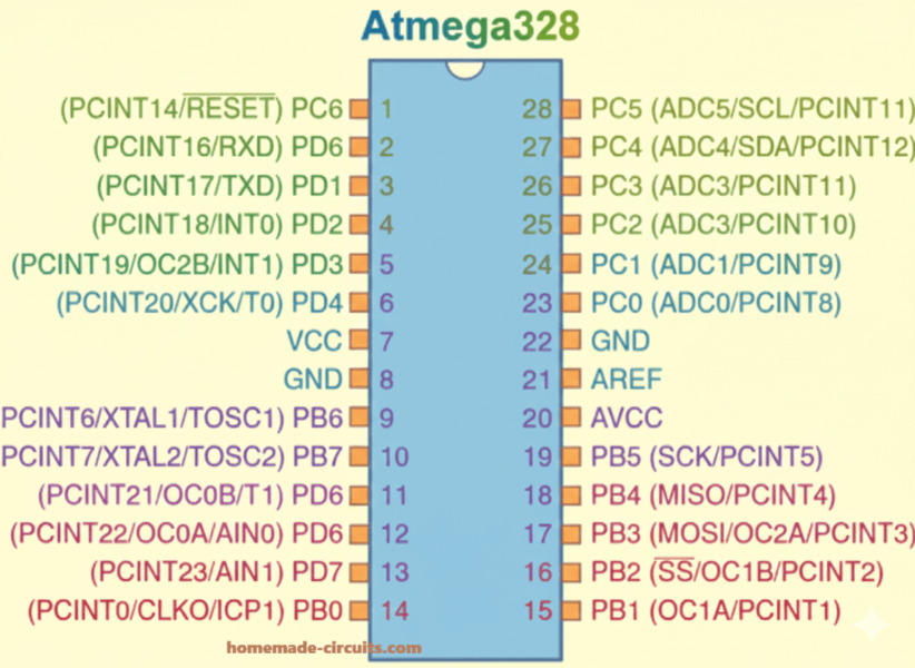
ATmega MCUs come in DIP package and also SMD package, so pin layout changes physically but functions remain same. One pin usually does more than one job depending on configuration.
- VCC is for power supply
- GND is ground
- PORTB, PORTC, PORTD are general purpose IO ports
- RESET is used to reset the MCU
- XTAL1 and XTAL2 are for external crystal
- AVCC is power supply for ADC
- AREF is reference voltage for ADC
Each port pin internally works using three registers and these are very important.
- DDRx decides whether pin is input or output
- PORTx is used for output or enabling pull-up
- PINx is used for reading input
Clock Source Options
ATmega can run with different clock sources depending on requirement.
- Internal RC oscillator
- External crystal oscillator
- External ceramic resonator
- External clock source
By default, most ATmega MCUs come set to use internal 1 MHz or 8 MHz oscillator. Which clock is selected is controlled by fuse bits, hence fuse bits are very important here.
Basic Hardware Setup
Minimum Circuit to Run ATmega
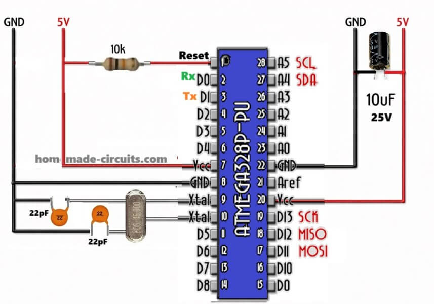
To just make ATmega run properly, we do not need many components, just the following.
- ATmega MCU
- 5 V regulated power supply
- 100 nF decoupling capacitors near VCC and AVCC
- 10K pull-up resistor on RESET pin
- clock source only if internal oscillator is not used
Power Supply
Always use regulated 5 V supply. AVCC must be connected even if ADC is not used, many beginners forget this and then MCU behaves strangely. AREF should be connected to ground using a 100 nF capacitor.
ISP Programming Connections
In-System Programming uses SPI pins and these pins must be connected correctly.
- MOSI
- MISO
- SCK
- RESET
- VCC
- GND
These pins go to USBasp or USBtiny programmer for programming.
- Required Software Tools
For programming ATmega without Arduino, these tools are required.
- AVR-GCC compiler
- AVRDUDE programming software
- Text editor or IDE like Microchip Studio
- USBasp or compatible ISP programmer
Installing AVR-GCC
If you are using Windows then easiest way is Microchip Studio or WinAVR.
If you are using Linux, you can install avr-gcc and avrdude using package manager.
Programming Methods
ISP Programming
This is the most common method. Program is written directly into Flash using SPI interface.
Bootloader Programming
Here a bootloader is already present, so you can program using UART or USB without ISP programmer.
High Voltage Programming
This is used when fuse bits are set wrongly and MCU is locked, so recovery is done using high voltage.
Understanding Fuse Bits
Fuse bits control hardware behavior, not software logic. So you must be careful.
- Fuse bits control clock source
- Fuse bits control clock divide by 8
- Fuse bits control brown-out detection
- Fuse bits control reset pin enable or disable
Fuse bits are not part of Flash program memory, so they must be set separately and carefully.
Example fuse settings for internal 8 MHz clock.
- CKSEL set to Internal oscillator
- CKDIV8 disabled
Basic Programming Structure
AVR programs are written in C language using avr-libc. Structure is always similar.
- Include required headers
- Define CPU frequency
- Configure registers
- Use main loop
Example LED Blinking Program
This example blinks LED connected to PB0.
Code remains same:
#define F_CPU 8000000
#include <avr/io.h>
#include <util/delay.h>

int main(void)
{
DDRB |= (1 << PB0);
while(1)
{
PORTB |= (1 << PB0);
_delay_ms(500);
PORTB &= ~(1 << PB0);
_delay_ms(500);
}
}
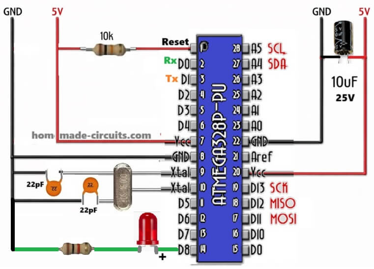
How it Works
We want to blink LED, so we connect LED to PB0, then we control it by software, now we define CPU clock so _delay_ms works right.
Code works like this, we first tell DDRB that PB0 is output, then in loop we turn PB0 high, wait 500 ms, turn PB0 low, wait 500 ms, then repeat forever. That’s simple blink.
Registers: DDRB sets PB0 as output, PORTB controls HIGH or LOW, _delay_ms gives delay using CPU clock, now we see LED blink like heartbeat.
Digital Input Example
Here we read a push button on PD2 and control LED on PB0.
Code remains same:
#define F_CPU 8000000
#include <avr/io.h>
#include <util/delay.h>

int main(void)
{
DDRB |= (1 << PB0);
DDRD &= ~(1 << PD2);
PORTD |= (1 << PD2);

while(1)
{
    if(!(PIND & (1 << PD2)))
    {
        PORTB |= (1 << PB0);
    }
    else
    {
        PORTB &= ~(1 << PB0);
    }
}
}
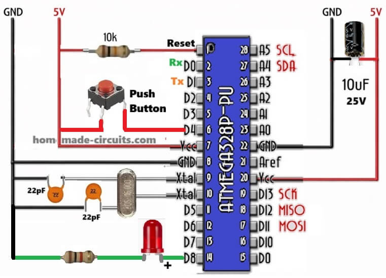
In the above code we read push button on PD2, LED still on PB0. So we need input pin, we do DDRD &= ~(1 << PD2) to make PD2 input, then we enable pull-up by PORTD |= (1 << PD2) so button reads HIGH when not pressed.
In loop we check button, now if(!(PIND & (1 << PD2))) then button is pressed, we set LED ON by PORTB |= (1 << PB0), else LED OFF by PORTB &= ~(1 << PB0).
So now we can press button, LED reacts, simple input-output.
Timer Programming Example
Here Timer0 is used to generate periodic interrupt.
Code remains same:
#include <avr/io.h>
#include <avr/interrupt.h>

ISR(TIMER0_OVF_vect)
{
PORTB ^= (1 << PB0);
}

int main(void)
{
DDRB |= (1 << PB0);
TCCR0 |= (1 << CS02) | (1 << CS00);
TIMSK |= (1 << TOIE0);
sei();

while(1)
{
}
}
In the above program we want automatic blinking without delay, we use Timer0 overflow interrupt, so every time timer overflows, ISR runs.
ISR(TIMER0_OVF_vect) just toggles PB0 by PORTB ^= (1 << PB0), that flips LED.
In main we set PB0 output, set timer prescaler TCCR0 |= (1 << CS02) | (1 << CS00), enable Timer0 overflow interrupt TIMSK |= (1 << TOIE0), enable global interrupt by sei(), then loop does nothing, ISR handles blinking.
Now LED blinks by timer, not blocking code, so we can do other things, that looks cool, right?.
ADC Programming Example
Here we read analog voltage from ADC0.
Code remains same:
#include <avr/io.h>

void ADC_init(void)
{
ADMUX = (1 << REFS0);
ADCSRA = (1 << ADEN) | (1 << ADPS2) | (1 << ADPS1) | (1 << ADPS0);
}

uint16_t ADC_read(void)
{
ADCSRA |= (1 << ADSC);
while(ADCSRA & (1 << ADSC));
return ADC;
}

int main(void)
{
ADC_init();
while(1)
{
uint16_t value = ADC_read();
}
}
As shown in the code above, we want analog read from ADC0, first we init ADC, ADMUX = (1 << REFS0) selects AVCC as reference, ADCSRA = (1 << ADEN) | prescaler selects speed, enable ADC.
To read we set ADSC start conversion, wait while ADCSRA & ADSC is busy, then return ADC result.
In main we call ADC_init(), then loop forever read ADC_read() to get analog value into uint16_t value.
Now we can measure voltage, sensor data, etc.
UART Programming Example
This example sends data through serial communication.
Code remains same:
#include <avr/io.h>

void UART_init(unsigned int ubrr)
{
UBRRH = (unsigned char)(ubrr >> 8);
UBRRL = (unsigned char)ubrr;
UCSRB = (1 << TXEN);
UCSRC = (1 << URSEL) | (1 << UCSZ1) | (1 << UCSZ0);
}

void UART_transmit(unsigned char data)
{
while(!(UCSRA & (1 << UDRE)));
UDR = data;
}

int main(void)
{
UART_init(51);
while(1)
{
UART_transmit('A');
}
}
In this code we want to send data over serial, so we init UART by setting UBRR high and low bytes for baud rate, UCSRB = (1 << TXEN) enables transmitter, UCSRC sets frame 8-bit data.
To send data we wait until transmit buffer empty by while(!(UCSRA & (1 << UDRE))) then write data to UDR.
In main we init UART with 51 (for 9600 baud at 8MHz), then loop forever send 'A'. Now serial terminal can see 'A' repeating.
Low Power Sleep Modes
ATmega supports many sleep modes like idle, power down, power save and these help in reducing power consumption a lot especially for battery based projects.
Debugging Tips
- Always check power supply first.
- Then make sure to verify fuse bits.
- Remember to confirm clock source.
- Use LED or UART output for debugging step by step.
Conclusion
ATmega microcontrollers are very powerful and flexible and also beginner friendly if you learn registers properly. When you understand clock configuration, fuse bits, and peripherals then you can design professional embedded systems without Arduino abstraction layer. Once you master ATmega programming, you get full control over hardware and your embedded design skills improve strongly and clearly.

Need Help? Please Leave a Comment! We value your input—Kindly keep it relevant to the above topic!