MOVs or metal oxide varistors are devices designed for controlling mains switch ON surges in electrical and electronic circuits. Selecting an MOV for a particular electronic circuit might require some consideration and calculation, I have explained the procedures here.
What are MOVs
Metal oxide varistors or simply varistors are non-linear surge suppressor devices which are used for suppressing sudden, high abnormal voltage transients or surges, especially during power switch ON or thunder lightening situations.
These are mostly used in sensitive electronic circuits for safeguarding against such catastrophic occurrences.
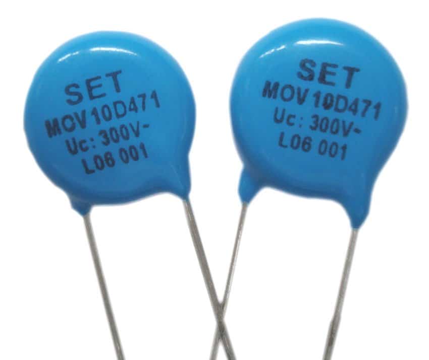
MOVs are basically non-polar, voltage dependent devices, meaning these devices will react to changes in voltage conditions.
Therefore MOVs are specified to trigger ON whenever the rated magnitude of voltage across their connections is exceeded.
This voltage rating at which an MOV may be rated to fire and short the transient to ground is called its clamping voltage specification.
For example, if suppose the clamping voltage rating of an MOV is 350V then it will switch ON whenever the voltage across it surpasses this limit.
When an MOV switches ON or is triggered by a high voltage surge it shorts the voltage spike across its terminals, preventing it from entering the vulnerable electronic device attached on the other side.
This action protects the electronic circuit from such accidental voltage surges and transient spikes.
And since the above reaction is sudden, MOVs are characterized as non-linear devices, which implies that these will not vary their characteristics gradually but suddenly when the specified parameters is exceeded.
The best characteristic of an MOV is its ability to absorb high current content accompanied with the voltage surge . Depending on the MOV specification the current absorbing capacity of an MOV could be anywhere between 1 amp to a massive 2500 amps
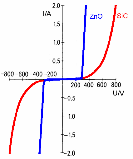
Current-voltage characteristic waveform of a typical zinc oxide MOV
However the duration of the current handling feature of an MOV may be limited to a few microseconds only, which means the activation of an MOV under such sever situations can not be more than a few microseconds, otherwise it could burn the device and damage it permanently.
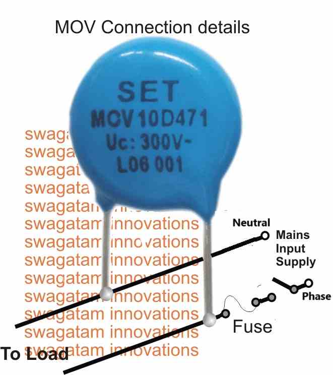
Therefore it is advised to use a fuse in series with the mains line in conjunction with the attached MOV for ensuring safety to both the electronic circuit and also to the MOV under a possible extreme catastrophic conditions.
ELECTRICAL CHARACTERISTICS
Typically the V/I characteristic of a ZnO varistor (MOV) can be understood with the following explanation:
The relationship between voltage and current of a varistor can be roughly estimated with the following formula
V = C x Iβ
where:
V = Voltage
C = Varistor voltage at 1 A
I = Actual working current
β = Tangent of angle curve deviating from the horizontal
Practical Example
When:
C = 230 V at 1 A
β = 0.035 (ZnO)
I = 10-3 A or 102 A
V = C x Iβ
so that for current of 10-3 A: V = 230 x (10-3)0.035 = 180 V and
for a current of 102 A: V = 230 x (102)0.035 = 270 V
Source: https://www.vishay.com/docs/29079/varintro.pdf
How to Select an MOV
Selecting an MOV for a desired application is actually easy.
First determine the maximum peak safe operating voltage of the electronic circuit which needs the protection and then apply an MOV specified to conduct near about this voltage limit.
For example, suppose it's an SMPS device with a max capability of 285V RMS from the mains input, implies that the unit would be able to handle a peak mains surge of not more than 285/0.707 = 403V
The 403V figure provides us the max peak mains handling capacity of the SMPS circuit which must be avoided under any circumstances and therefore an MOV rated with a clamping voltage of around 400V could be applied to this SMPS safely.
The current rating of the MOV could be twice that of the SMPS rating, meaning if the SMPS wattage is rated at 24 watts at the secondary, then the primary could be calculated as 24/285 = 0.084 amps, therefore the MOV current could be anywhere above 0.084 x 2 = 0.168 amps or 200mA.
However a 200mA MOV could be difficult to obtain therefore a standard 1 amp device could be used for serving the purpose with utmost efficiency.
Note: Many countries have adopted a harmonized standard for AC power grid voltage typically around 230V with a tolerance of +10% and -6%. This means, the acceptable voltage range can fluctuate between 207V and 253V. Previously, some regions might have had a nominal voltage of 240V with an upper limit of 264V. However, under the new standard, the upper limit would be 253V. Therefore varistors rated for 270V or 275V could be suitable for protecting against voltage spikes in these regions.


Questions & Answers
I didn't knew about MOV and seen them only on PC SMPS and PC UPS but now i know what it is and how to use it, thank you very much sir, i am learning a lot from your great site.
you are most welcome Lima…
hi sir i just want to ask on how to replace an mov that burn on the board an no details?
Please tell me the technical details of the unit, based on that I can suggest the method…
Dear Swagatham
The clamping voltage can be understand from the printing on the body.(eg:300v in the above image).
But, how can uderstand current rating of a MOV…..?
Thanks
Dear Anil, Current is not printed on the body but can be found from the available charts, the current is normally fixed at 1 amp for regular MOVs, because since the average fluctuations are in microseconds a 1 amp value is able to sink it comfortably, even if the input current is much above this value, meaning if the input voltage rises to 600V with 100 amps for 1 microsecond, the 1 amp MOV will be able to tolerate it and sink it safely…
Dear Swagatham, thanks a lot for the reply…
You are welcome Anil!
Dear Swagatam,
A very informative & great site for learning a lot with simple approach.
SsinivasanBashyam
Thank you dear Srinivasan, I am so glad you liked my site!! Please feel free to comment for any circuit related doubts or queries…
Your site is a gift from God which has a lot of very useful informations very easy xplanations and much more :
Thanks Charles, I am glad you liked my site…keep up the good work!
Thank u sir tis sure i will continue to be in your site to learn as much as possible, sir may i know which country u belong to
You are welcome Charles, I am from india…
Sir, thank u very much for the response am very glad to hear that we are in India, ur english is extreme, sir will u pl guide me where i can make or get pcb’s for ur ckts, thank u.
Thanks Charles, I am sorry I won’t be able to help with the PCB, I think you should inquire this in your local market and see if anybody is involved with this job….
is it logical to put mov in the output of an alternator going to the voltage reg. if the alternator is frequently switch on and off. and also in the input of a 3 phase motor if also frequently switch on and off. or what can i put to protect the voltage reg and battery from unwanted voltage spikes and also the speed controler if frequently switch on and off this motors. ur site is very helpfull to us. more knowledge to you and good health
Thank you Ralph, I am glad you are finding my website useful.
Yes definitely an MOV can prove useful at the output of an alternator, just as it does across Mains inputs of common electrical gadgets.
Additionally you can put combinations of high value and low value capacitors at the input and output of the voltage regulator to provide extra protection against switching spikes…
Thanks for the reply. Is there a specific value for mov to b use in alternator. What value will i use. Will the motor or alternator not be damage In frequent on and off the switching timing is around 10milisec
You can use a value that may be slightly higher than the peak value of the alternator, for example if the peak AC is 330V from the alternator, you can select an MOV rated at 360V
Hello, sir. Thanks for your good and helpful posts.
You are most welcome!!
Sir, how to prosecute it. This good, good work takes a lot of time. Big thanks again for all your posts.
It’s my pleasure Marian, yes it definitely takes a huge amount of effort and years of hard work to do this…I appreciate your thoughts!!
Thank u sir sure i will continue to be in your site to learn as much as possible. As you say if we have any circuit related questions ; you are most happy to help! So that i do have suffer about over voltage & at spike voltage that burns our control module of generator & contactor coils. our in put voltage is 1 phase /3 phase , 220 v /380 V. So do you have a simple ckt to regulate this in put. 10Q in advance.
Thank you Ze Aman, If your conactor is burning then it means it is not sufficiently rated. You will have to upgrade the contactor rating according to the switch ON surge current specifications of the generator. AS for the module issue, I can suggest only once I know all the electrical details of the module
I use to follow your site quite often.Most of your circuit is interesting to follow.I am an electronic Engineer too.I am running an Electronic Hobby Tutoring under the name “GRS Electronics”.If you could share me your Cell phone number it would be very helpfull sir.
Regards,
GRS Electronics.
Thank you, I appreciate your thoughts very much, however interacting through phone won’t be possible, if you have any questions you can ask through comments here!
Muy útil el contenido de tus post. Gracias por compartir.
Glad you liked it Ernesto!!
Thank you very much for your technical assistance.I always have voltage surge,which end up damaging my electronics. How do I stop this?
If it’s happening frequently then you may need one of these designs:
https://www.homemade-circuits.com/highly-accurate-mains-high-and-low/
Thank you very much. You have saved me from further damage on my electronics.
No problem!
Dear Swagatam,
I have been following you since quite some time on your website.
I would say, it is wonderful resource.
I have few design requirements / problems for which I need your assistance. Can you please let me know if there is any way to connect with you ?
Like on Quora / Facebook / Email – anything ?
Thank you 🙂
Thanks Dear Nameer, I normally discuss only through comments in this website, but the comments must be posted under related articles only.
Hello Swagatam,
The article is very good. Thanks.
Can you please help on how the number of spikes are calculated for any given MOV? For example, if we select a 14mm MOV, 320V AC where 2.5KV surge is required. How can we define, how many surge strikes of 2.5KV the MOV can handle?
Thank you Rishi, I could not find this information anywhere, so according to me the number of strikes do not matter as long as the duration is very small and within the tolerable limit of the device. The device will start deteriorating only when the spike duration exceeds the tolerable limit.
Here’s one article which has some good relevant information
https://ieeexplore.ieee.org/document/7800668
The following image shows the approximate endurance capacity of a standard MOV as suggested by a few reputed manufacturers
Hi Sir,
I’m about to convert a dewalt dcb115 110v charger to 220v.. right now i identified to change the values of the capacitor from 200v 220uF to 400v 150uF. i will also add two ceramic type resistor with 5W 0.33ohms… thinking of adding a MOV but i dont know the exact rating to buy.. pls help. im not sure it would help my circuit. Im not sure also if i need to replace other components aside from those 3 i mentioned above. appreciate your help on this please.
Hi Mark, if there are any more capacitors you may have to change all those with higher voltage rated ones, appropriately.
For the MOV you can use a 400V MOV
Thanks for the response Sir.
Hello Swagatam,
I have this big 5HP motor 1PH , 240VAC which is powered ON and OFF by a pressure switch ( it’s an air compressor). The switch contacts are gone and replacement cost a fortune. So I decided to clean the pressure switch contacts and use it to trigger a big SSR of 100Amps. I know that this type of load is quite inductive and therefore I have to protect my SSR from voltage spike when it will turn OFF. I think an MOV would be the ideal device. The motor receive 244VAC (345Vpeak) , my SSR is rated at 380VAC (537Vpeak). So, what voltage should be used for determining the correct MOV specification ? I am a bit lost concerning which voltage to use. I know that the maximum permitted voltage on the SSR is 537V . Should the MOV be rated at 345V or 537V ? Thanks for your advice.
Hello Fred, SSR already have internal snubbers for extreme protection against motor back EMFs, however for extra protection you can add a 345V at the input supply side, use two of them in parallel if possible.
Hi,
We are looking for one MOV to protect our 24 V DC ckt, Will u please advise us on that.
Thanks
Ajay
Hi, you can connect the MOV on the AC side, right across the phase/neutral entry points of the circuit. The MOV can be a rated at 330V
I couldn’t find so called next article where it is discussed regarding how to select MOVs and learn the same in details through charts and tables. Can you pl. mention which article you are talking about?
You can refer to the following datasheet to see the chart of the MOV, I’ll try to post the article soon if it is possible:
https://www.homemade-circuits.com/wp-content/uploads/2021/04/MOV-chart_compressed.pdf
Hi Swagatam,
Interesting article and good explanation. But I still have problems choosing the right replacement MOV Varistor for my circuit board (it is a chiller-airco unit on board of a boat). The Varistor is blown because of a voltage spike from the power socket in the harbour (probably more than 260V). I can read on the green-coloured Varistor a few numbers and letters: 430NR and Sp and like 73 or 76 or 78, it is about 15mm dia and 5.5mm thick. The airco unit is automatic fused at 35amps. The harbour delivers 230V but I can see that it is most of the time around 240-250V and sometimes 250-260. I was looking at replacement Varistor Bourns MOV-14D431K but I am not sure if I have the correct one. Or VDRUS14X175BSE VARISTOR, MOV, 275V, DISC 14MM VISHAY?? Can you help me out here? Thanks, Jeroen
Thank you Jeroen, according to the chart provided in the following article, the varistor VDRS14T275xyE seems to be a good choice. It is rated at 275 V continuous voltage and 430 max clamping voltage. The current is specified at 50 amps but I am not sure what is duration of this current supposed to be.
https://www.vishay.com/docs/29081/vdrs.pdf
Thank you for your extremely informative and to the point articles and advice.
A power extension strip burnt out today and when I opened it I found that one of 3 MOV’s had flashed and burnt out, along with the adjacent switch.
I want to replace the MOV and would be grateful for your advice. The equipment in use from the extension are a flat screen TV, Amazon Firestick, laptop charger etc. Would a clamping voltage of 300 or 350 volts be sufficient, or is that too low? Current rating of one amp?
Thank you