Voltage spikes can sometimes be a big nuisance as far as the safety of the various electronic appliances are concerned. I have explained how to make a simple AC Mains surge protector circuits at home.
What is a Surge Protector
A surge protector is an electrical device which is designed to neutralize minor electrical spikes and transients that normally keep appearing in the mains utility lines.
These are normally installed in sensitive and vulnerable electronic equipment to prevent them from getting damaged due to these sudden unprecedented surges and voltage fluctuations.
They work by instantaneously short circuiting any excess high voltage that may appear in the mains AC line for a very duration.
This duration is usually lasts in microseconds. Anything above this period of time may cause the surge suppressor itself to burn or get damaged
What is Voltage In Rush
A sudden voltage spike is basically a sharp rise in the voltage lasting not more than a few milliseconds but enough to cause damage to our precious equipment almost instantly.
It thus becomes imperative to stop or block these from entering vulnerable electronic gadgets like our personal computers.
Commercial spike busters are though available pretty easily and cheaply too, cannot be trusted and moreover have no reliability test arrangement so it becomes just a "assuming" game, until it's all over.
Working Design
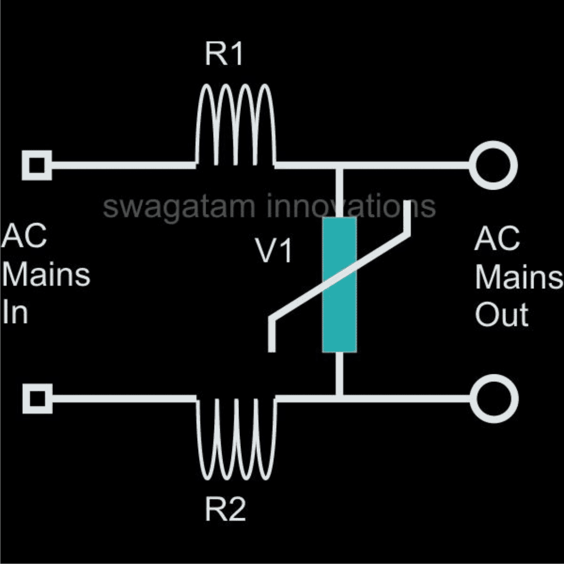
The circuit of a Simple AC Mains Surge Protector Device below, which shows how to make a simple homemade AC mains high current protector device is based on very simple principle of "speed breaking" the initial jolt through components who are well equipped in the field.
A simple iron resistor and MOV combination are more than enough to provide the protections we are looking for.
Here R1 and R2 are 5 turns of iron wire (0.2mm thick) over a 1 inch diameter air core each followed by an appropriately rated varistor or an MOV connected across them to become a full fledged spike protector system.
Sudden high AC entering the input of spike are effectively tackled and the "sting" absorbed in the course by the relevant parts and a safe and clean mains is allowed to go through the connected load.
Metal Oxide Varistor (MOV) Calculations and Formulas
The calculation of energy during application of such a pulse is given by the formula:
E = (Vpeak x I peak) x t2 x K
where:
Ipeak = peak current
Vpeak = voltage at peak current
β = given for I = ½ x Ipeak to Ipeak
K is a constant depending on t2, when t1 is 8 μs to 10 μs
A low value of β corresponds to a low value of Vpeak and then to a low value of E.
Transient Protector Using Inductors and MOV
Question Regarding Surge Prevention in Electronic Ballast
Hi swagtam, I found your email address from your blog. I really need yr help.
Actually my company has customer in china we make UV lamps and we use electronic ballast for it.
Now the problem is in china because of Over Voltage the ballast burn out so i design circuit which is in attachment which doesn't help either?
So I found your Ultimate High/Low Voltage Protector Circuit which i wants to build. or can you tell me the update if i can do in my circuit that will be great.
Solution
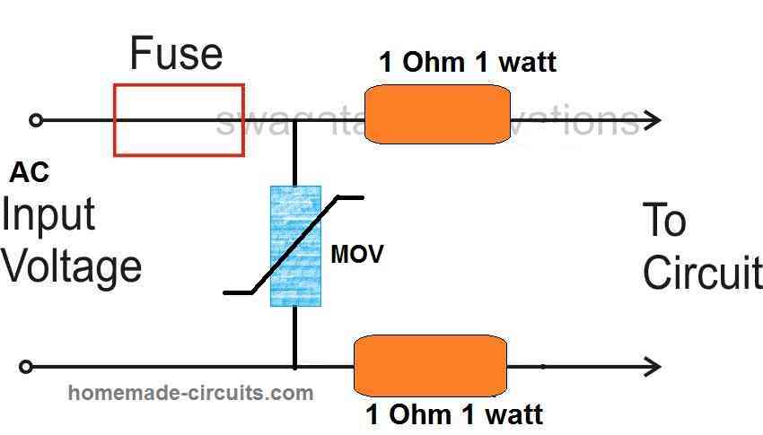
According to me the problem may not be with the voltage fluctuations, rather it's because of the sudden voltage surges that's blowing of your ballast circuit.
The diagram shown by you may not prove very effective, because it does not incorporate a resistor or any kind of barrier with the MOVs.
You may try the following circuit, introduce it at the entry point of the ballast circuit.
Hope it works:
Using an NTC and MOV
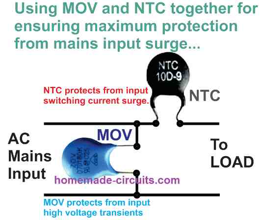
The following image shows how two different sudden high voltage suppressor devices could be tied up with the mains line for achieving a double edged safety.
The NTC here enables an initial switch ON current in rush protection by offering a higher resistance due to its initial lower temperature, but in the course of this action its temperature begins increasing and it begins allowing more current for the appliance until a normal working conditions achieved.
The MOV on the other hand complements the NTC output and makes sure that in case the NTC is unable to stop the up-surge onslaught correctly, it switches ON itself shorting the residual high transient content to ground and as a result establishing a safest possible supply for the connected load or the appliance.
Highly Recommended for you: 220 V AC Filter Circuit
Formulas for Calculating MOV and NTC Parameters
NTC (Negative Temperature Coefficient) Thermistor Formulas
Resistance-Temperature Relationship (NTC Thermistor)Using the Beta Parameter Equation:
R(T) = R0 * e(β * (1/T - 1/T0))
Where:
- R(T) = resistance at temperature T (in ohms, Ω)
- R0 = resistance at a reference temperature
- T0 (in ohms, Ω)
- β = material constant (in K)
- T = temperature in kelvins (K)
- T0 = reference temperature in kelvins (K), usually 298 K (25°C)
Using the Steinhart-Hart Equation (more accurate):
1/T = A + B * ln(R) + C * (ln(R))3
Where:
- T = temperature in kelvins (K)
- R = resistance at temperature T (in ohms, Ω)
- A, B, C = constants that depend on the specific thermistor.
Thermal Time Constant (NTC Thermistor)τ = (Cth * R) / P
Where:
- τ = thermal time constant (in seconds, s)
- Cth = thermal mass of the thermistor (in joules per degree Celsius, J/°C)
- R = resistance of the thermistor (in ohms, Ω)
- P = power dissipated by the thermistor (in watts, W)
Inrush Current Limiting (NTC Thermistor)I(t) = V / R(T(t))Where:
- I(t) = current at time t (in amperes, A)
- V = supply voltage (in volts, V)
- RT(t) = resistance of the thermistor at the temperature T(t) (in ohms, Ω)
Additional Formulas:
MOV:
Voltage-Resistance Relationship:
R(V) = (Vr2) / (V2 - Vr2) * Rmax
Energy Absorption:
E = 1/2 * C * Vmax2
Clamping Voltage:
Vclamp = Vr * (I / Irated)α
NTC Thermistor:
Beta Parameter Equation:
R(T) = R0 * e(β * (1/T - 1/T0))
Steinhart-Hart Equation:
1/T = A + B * ln(R) + C * (ln(R))3
Thermal Time Constant:
τ = (C_th * R) / P
Inrush Current Limiting:
I(t) = V / R(T(t))
RFI Line Filter and Surge Suppression Circuit
If you are looking for a mains AC line filter circuit having a combined protection against radio frequency interference (RFI) suppression, along with voltage surge control, then the following design could prove quite handy.
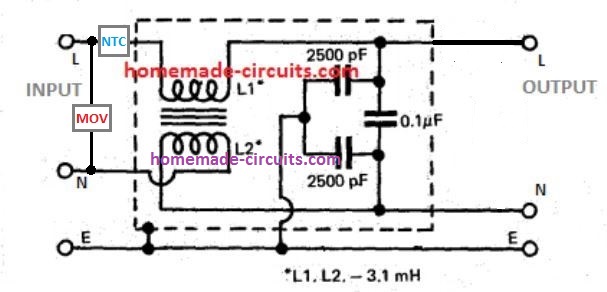
As we can see, the input side is protected with an NTC and MOV. The MOV grounds any instantaneous over voltage surge, while the NTC limits an over current surge.
The next stage constitutes an RFI line filter, comprising of a small ferrite transformer and a few capacitors.
The transformer arrests and blocks the passage of any incoming or outgoing RFI across the line, while the capacitor network reinforces the effect by grounding the residual high frequency content across the line.
The transformer is built over a small ferrite rod, having two identical winding wrapped one over the other, and one of the winding end connections swapped between the input/output Neutral line.



Questions & Answers
You can incorporate thermistors and MOVs together, resistors can be avoided then.
for knowing more about thermistors, you may refer to this article:
https://www.homemade-circuits.com/2013/02/using-ntc-resistor-as-surge-suppressor.html
For what application do you want to use it?
No it's not due to spike, it's due to a split second late response from the UPS, try with a new good quality UPS and you won't find this issue happening.
telephone surge protector?? i didn't get the application, can you pls explain it?
Hi….Swagatam can u give the VA rating of mov & fuse of above ckt u used above….when my ckt I/p current is 130mA and o/p current is 170mA & o/p voltage is 167 when I/p voltage is 230V for electronic ballast. ….so please share it with me asap….
Hi Shersingh,
you can use a 350V RMS, @5amp rated MOV.
Hi,
Is it possible to use this diagram for a single wire ground return system? My power line is a single phase 240V and the neutral is coming from a copper rod in the ground. The voltage fluctuates a lot and i would really like to protect my devices (Mainly motors and VFD's) and some computers. Do you recommend any other systems like high and low surge protection? Also, what protection rating should i expect (high voltage vise)
I appreciate your response in advanced.
Chris
Hi,
the above circuit will only help to control surge in-rush to some extent but won't control the voltage fluctuations.
you would need a voltage stabilizer circuit for tackling the issue effectively, one design has been discussed below which may be tried or procured readymade:
https://www.homemade-circuits.com/2011/12/how-to-make-accurate-7-stage-op-amp.html#uds-search-results
Hi Swagatam ,
How are you ? hope doing well.
If want to draw constant 220 v AC at any point
Generally input is
Low – 110v / 130v AC
High – 230/260 v AC
Required Output
220 V AC (Stabilized)
Can you please suggest best circuit . if Tranformerless will preferable.
Thanks
Nilesh Patil
Hi Nilesh,
I am fine, thanks!
You can try the design that's shown in the following article:
https://www.homemade-circuits.com/2011/12/how-to-make-accurate-7-stage-op-amp.html#uds-search-results
a transformerless design could be very difficult since it would involve complex mosfet drivers, ferrite inductors etc, so I think using the traditional iron core transformer would be much easier, although a little bulky.
Plz. value of MOV and best one company product……thnx.
company is not important as all are good, the clamping voltage rating should be 50 V more than the input mains supply voltage.
Value of MOV and best company product….thnx.
Hi Mr Swatam. Cogratulation for your extraordinary electronic web page…….
I write from México. My question is: For a 120v nominal voltage, what should be the value of the resistors, and the maximun peak voltage and Joules for the MOV's ?
Thanks in advance for your help…….
Thanks Roberto,
for 120V you can select 200V as the clamping voltage for the MOV, the resistors are not critical they are just for complementing the MOVs, any value between 0.5 ohms to 1 ohms will do the job.
10 ohm is far too big and must not be used, it's incorrectly shown in the diagram.
Hi Mr. Swatam, do you have a schematic diagram for TVSS or SPD for resedential use only. pls include the value of materials.
thank you so much.
Hi Cloyd,
you can probably try using the devices explained in the following article:
https://www.homemade-circuits.com/2015/01/high-power-industrial-surge-suppressor.html
put these directly across the wires that enter the house wiring.
the value can be of 350V/50amp
Hi Sir Swagatam, thank you for your response. i want to ask you more question sir about TVSS/SPD , This is for our thesis sir and i'm hoping that you can give us more details about the connection. we are troubling of our design sir because we would like to make a TVSS device that will connected parallel to the source (40A Breaker), thus we doubted our design due to its connection if it can really suppress the voltage surge. i will show you our design sir and were hoping that you can give us some advice on how to fully get the right design.
thank you for your time sir Swagatam, best regards.
Hi Cloyd,
The link which I suggested you in the earlier comment can be effectively used as a transient voltage surge suppressor.
Other option is in the form of diodes which is explained here, these also need to be connected parallel to the input mains supply:
https://en.wikipedia.org/wiki/Transient-voltage-suppression_diode
The image provided by you is not opening, please make it "public" by selecting the share option.
this is the diagram of our device sir.. the source is Line to Line. we just put the ground into the device for the MOV's.
https://drive.google.com/open?id=0B786VWhN4zxiTzlmeUhQRml4R2M
…please toggle the share option…
The upper diagram sir is what we wanted to do (parallel to the source) but we are not sure if it can supress the voltage surge thats why we decide to design another (lower diagram) which is connected in series from the source. i'm begging for your expert suggestion and advice sir that can help a lot to our device to function and for us to pass the subject. thank you sir SWAGATAM.
normally all TVSS devices are extremely reliable and can be trusted for the necessary actions.
you can refer to the following article for more info:
https://www.homemade-circuits.com/2014/09/testing-mov-metal-oxide-varistor-surge.html
Dear Mr Swagatam
Firstly thank you for this great website, i have built a few small projects of your design, i have become extremly interested in transient voltage and the long term damage it does. I will test the above circuit and give some feed back.
What i would like to ask is (if you perhaps have an existing) a design where one can "monitor" the transient voltage on a incoming line (the main grid). I understand that there are "in line counters". This can be a great tool to take the readings before and after the unit install.
Will this be possible?
Again thank you for the great site and info.
Best Regards
Mark
South Africa
mrmcon@gmail.com
Thank you dear Mark,
The simplest way could be to connect a digital ammeter in series with the MOV that may have a feature to latch up to the reading corresponding to the transient value each time power is switched ON.
If it's possible I'll try to design and post it for you.
Thank you very much Sir.
ko good, but we want buy pcg/ components/ etc in india. is it possible in india?
yes, it' possible.
Hello!
A friend of mine was thinking of building a surge suppressor and voltage regulator by using ARM microprocessor. He was thinking of using inductor plus MOVs together. Do you think it is feasible?
Thank you.
Lim.
Hello,
MOVs don't require any external triggering circuit for activating, it's a self-actuated device so I don't think an MCU could be used for operating an MOV
Hi Swagatam,
I was looking for a surge suppressor device circuit diagram and was directed to your site. Upon reading about you and going through the comment and replies between you and your readers, your patience in answering all the queries really put me in great admiration to you. I came across so many people like you in the web but you are different from them, they can't respond.
Recently I just decided to become a hobbyist in electronics although I don't have a formal education or training about it but a steward/stewardess can land a commercial plane with the guidance of the ground controllers( this is from a movie).
I was inspired by a friend that showed me his DIY audio amplifier and it works well. I asked him for the details and he gave me copies of schematics, pcb layout, parts list as well as procedures of adjustments but it is limited to a 100W into 8ohm power. I want to evolve this to a 350W,8ohm design. The design uses 2SC5200 output devices and TIP41C drivers.
Can you give me suggestions, advices or even a new design from you, or, is it okey to publish the circuitry since it was designed by an EE in order for you to go through it and come up with solutions and recommendations to meet the desired power for my first project.
Actually I have already etched the pcb the very conventional way. By the way I am from the Philippines, work as a material eng'r in a construction company.
Nice knowing you Swagatam.
Your new reader/jollower,
Osic
Hi Osic, thanks so much! I appreciate your enthusiasm and wish you the very best!
Amplifiers can be quite difficult circuits as they require precision and balance at every node and stages of the circuit and so far I have not been able to master these gadgets due to their complex concepts and configurations.
So I am really sorry I won't eb able to assist you with amp designs, therefore I would recommend you to select a schematic which is originally designed to suit your specifications instead of modifying a design having a different specifications.
I have a 100 watt simple mosfet amplifier circuit in this site designed to work with around 35V normally which is capable of generating upto 300 watts power simply by using a higher voltage input of around 100V…however it requires a 4 ohm speaker, If you wish you could try that design also!!
Okay Swagatam I will take a look at your design. Thanks Swagatam, more power.
What MOV VALUE and part no
can be a 350V MOV
Hi Swagatam,
How are you,
A friend of mine had his TV friend due to a voltage surge,
Voltage Input from the mains line is 230V, sanctioned current is 6amps. want to help him out.
Can I use the circuit mentioned above 2 MOV with 10ohms 2 watt resistor,
-what should the value of the MOV be.
– what should the value of the fuse be in terms of AMPs.
– should a Indicator lamp be added in the circuit after the fuse,
Kindly advise.
warm regards
Thanks Patrick, I am good!
yes you can try it, just replace the resistors with 1 ohm 2 watt, because 10 could be a bit too high.
MOV could be rated at 350V (clamping voltage)
fuse could be an 8 amp rated….
indicator lamp is optional, it can be added for indicating a blown fuse
Hello Swagatam,
Thank you so much,
Apart from the Mains, it could be added in different sections of the house, where sensitive equipments are such as TV/ Music systems etc., just to be safe.
Is this okay ?
warm regards
Thanks Patrick, yes you can use an MOV with every appliance but MOV has its own restrictions too, for example it might not withstand the surge if it lasts for more than a millisecond, and could cause a short circuit and fire, therefore a series fuse also becomes mandatory.
Alternatively you can use a single powerful MOV near the main DP of the house, the MOV specs are I have explained below
https://www.homemade-circuits.com/2015/01/high-power-industrial-surge-suppressor.html
By the way all modern equipment already include a built-in MOV in their system
Hi Swagatam,
I'm planning to install a surge suppressor for the whole house at the mains AC panel (next to the meter board) is there a standard part available available off the shelf or do we need to design one and install. i was able to find CHSPT2MAX from Eaton, but its too expensive, any suggestions…
Hi Ravi, you an industrial MOV, in conjunction with the following delay ON relay crcuit, adjust the delay time to may be a second or so, and connect the relay contacts with the house wiring.
https://www.homemade-circuits.com/2013/02/make-this-simple-delay-on-circuit.html
Industrial MOV sample is discussed below
https://www.homemade-circuits.com/2015/01/high-power-industrial-surge-suppressor.html
I have an electronic digital calendar clock, its supply unit has bagged off three times due to surge voltage in the mains. I want to incorporate a simple sure suppressor for it. it may be drawing less than on ampere current. what value components are recommended. please advise me if any simplest circuit which I can assemble myself.
Normally any god power supply will never burn with minor supply fluctuations….what kind of supply unit have you been using? Is it SMPS based or transformer based?
I would suggest you to use your cellphone charger for the purpose which has all the protections in-built
still if you are interested to build your customized surge suppressor, you can try an NTC in series with any of the input mains supply lines, and additionally connect an MOV across the two supply lines after the NTC.
Namasthe,
I am talking about the " Ajantha make wall clock : OLC Quartz 104, Model. computer century Calendar", which I am using. There is a supply module inside the clock. Every time there is a power shout down in our area and the power comes up, the clock fails. The watch repairer says supply unit is burnt. So I just wanted to incorporate a surge suppresser to this clock externally.
OK I understood, the in-built power supply could be an SMPS based…..as expressed in above comment you can try connecting an NTC in series with any of the supply lines, and also connect an MOV across the two supply lines after the NTC.
I'll try to update the diagram soon for your reference
Hi sir,
I am designing a surge protection device for lightning. Is the design above is suitable for it? Can I replace the resistor with an inductor because i saw it somewhere in other website?
Basically my input supply will be 240 Vac, what is the value of clamping voltage of MOV is suitable? Can I use MOV with 240V clamping voltage?
Thanks!
Hi Voon, if the lightning strikes directly into the house wiring then no surge suppressor would be capable of stopping it.
MOV can suppress only minor electrical surges, not lightening related surges….to suppress lightning related surges the best idea would be to employ a triac based crowbar circuit as described here
https://www.homemade-circuits.com/2017/03/surge-arrestor-circuit-with-surge.html
the high voltage capacitor and diode can be ignored and removed.
you can also include an MOV/inductor suppresor as per your initial requirement in conjunction with the above design.
hi sir,
first i try to explain you my system….which is regarding to operate 3 phase submersible pump from gsm based remote and data accusation also….
in that metal sheet enclose contain electro-mechanical contactors, smps for gsm data logger for sms and gprs connectivity.
problem is —
1.some time when pump is off due to non power we found that when power comes suddenly electrical blast create in contactors at ac input terminals.
2. some time when starter strat, gsm electronic immediate shutdown or restart, due to this pump cant start.
3. in solar operated gsm logger , found that in rainy season modem became hang.
i think all above are due to electrical surge..
sir please guide me how to solve it, i want to make a spd solution for above …..
Hi Gajendra, for controlling surge you can try a delay ON timer circuit, as explained at the bottom section of this article:
https://www.homemade-circuits.com/simple-delay-timer-circuits-explained/
You can replace the relay with a 3 contact relay for connecting the 3 phase through the relay.
the delay ON could be set by adjusting the values of C2/R2. The emitter zener diode is not required and could be replaced with a wire link
Hello! I’ve got a somewhat complex question but not so difficult question that you can help me with. I’ll give you a little background as to WHY I am asking.
I have just moved into a new house that only has a 15amp circuit in the office. My wife’s computer equipment alone places a heavy demand on this circuit and I know that by adding my computer I would very easily overload it. To solve this issue I ran a dedicated circuit just for my equipment. My PC can be very power hungry depending on load as I am into water cooling overclocking, etc. I also know that PC power supplies are typically a little more efficient when operating at 240v than 120 and I figured while I was running a new circuit I could just as easily run two. I used #12 wire and ran two circuits. One is set up for 120v and has a 5-20R receptacle. The second I configured for 240v and has a 6-20R receptacle. This portion of the project is done, everything is hot, I only need to move in and hook up my equipment, I have the appropriate power cord to hook up my PC. I have been looking though and have noticed that many of my other components, such as my monitors will also operate on 240v so I figure why not run as much on 240 as I can?
Well as it turns out thus far the biggest reason why not is the ability to physically connect everything. My 240V circuit only has a single 6-20R receptacle and I have the need to plug in five or six devices. In the 120V world the simple solution is a power strip. I have had little success finding 240V power strips with 6-20R receptacles and those that I do find are $$$$. I figured I could build my own for a whole lot less money, or build a much superior product for the same money. A power strip is easy, but I figure if I’m going through the trouble I might as well build in surge protection and that’s where my lack of knowledge becomes a problem.
As I understand it European “200” volt systems are configured as a Hot-Neutral-Ground configuration with 200V from hot to ground or hot to neutral. In contrast my US configuration will be Hot-Hot-Ground with 240V with hot to hot and 120V from either hot to ground if that makes any difference at all in system design. I was thinking of creating some kind of a box with a “bus” system, consisting of a bar or terminal strip for each leg and the ground. This would allow me to connect multiple receptacles to the bus in parallel and thus not have the possibility of drawing excess current through any one receptacle.
Wish List:
1. Fused (or circuit breaker) protection for both hot legs. I’m thinking some kind of circuit breaker would be good so it could kill both legs in the event that one side has a fault, like a double pole circuit breaker.
2. High capacity surge suppression – Would it be more effective to have single surge protection point for the entire bus, or individual for each receptacle? My gut tells me that several smaller ones would be more effective than one large one but I could be dead wrong, I honestly do not know.
3. Visual indicator of surge suppression function.