Voltage spikes can sometimes be a big nuisance as far as the safety of the various electronic appliances are concerned. I have explained how to make a simple AC Mains surge protector circuits at home.
What is a Surge Protector
A surge protector is an electrical device which is designed to neutralize minor electrical spikes and transients that normally keep appearing in the mains utility lines.
These are normally installed in sensitive and vulnerable electronic equipment to prevent them from getting damaged due to these sudden unprecedented surges and voltage fluctuations.
They work by instantaneously short circuiting any excess high voltage that may appear in the mains AC line for a very duration.
This duration is usually lasts in microseconds. Anything above this period of time may cause the surge suppressor itself to burn or get damaged
What is Voltage In Rush
A sudden voltage spike is basically a sharp rise in the voltage lasting not more than a few milliseconds but enough to cause damage to our precious equipment almost instantly.
It thus becomes imperative to stop or block these from entering vulnerable electronic gadgets like our personal computers.
Commercial spike busters are though available pretty easily and cheaply too, cannot be trusted and moreover have no reliability test arrangement so it becomes just a "assuming" game, until it's all over.
Working Design
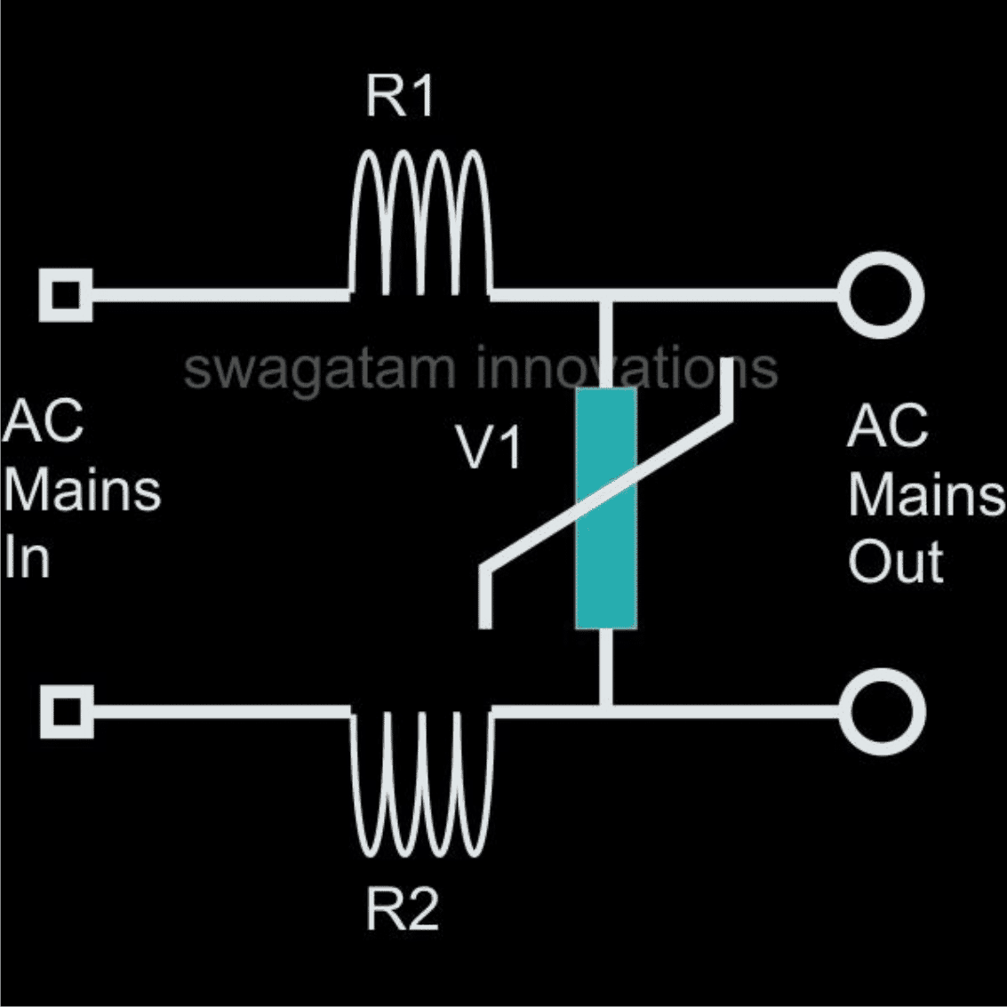
The circuit of a Simple AC Mains Surge Protector Device below, which shows how to make a simple homemade AC mains high current protector device is based on very simple principle of "speed breaking" the initial jolt through components who are well equipped in the field.
A simple iron resistor and MOV combination are more than enough to provide the protections we are looking for.
Here R1 and R2 are 5 turns of iron wire (0.2mm thick) over a 1 inch diameter air core each followed by an appropriately rated varistor or an MOV connected across them to become a full fledged spike protector system.
Sudden high AC entering the input of spike are effectively tackled and the "sting" absorbed in the course by the relevant parts and a safe and clean mains is allowed to go through the connected load.
Metal Oxide Varistor (MOV) Calculations and Formulas
The calculation of energy during application of such a pulse is given by the formula:
E = (Vpeak x I peak) x t2 x K
where:
Ipeak = peak current
Vpeak = voltage at peak current
β = given for I = ½ x Ipeak to Ipeak
K is a constant depending on t2, when t1 is 8 μs to 10 μs
A low value of β corresponds to a low value of Vpeak and then to a low value of E.
Transient Protector Using Inductors and MOV
Question Regarding Surge Prevention in Electronic Ballast
Hi swagtam, I found your email address from your blog. I really need yr help.
Actually my company has customer in china we make UV lamps and we use electronic ballast for it.
Now the problem is in china because of Over Voltage the ballast burn out so i design circuit which is in attachment which doesn't help either?
So I found your Ultimate High/Low Voltage Protector Circuit which i wants to build. or can you tell me the update if i can do in my circuit that will be great.
Solution
According to me the problem may not be with the voltage fluctuations, rather it's because of the sudden voltage surges that's blowing of your ballast circuit.
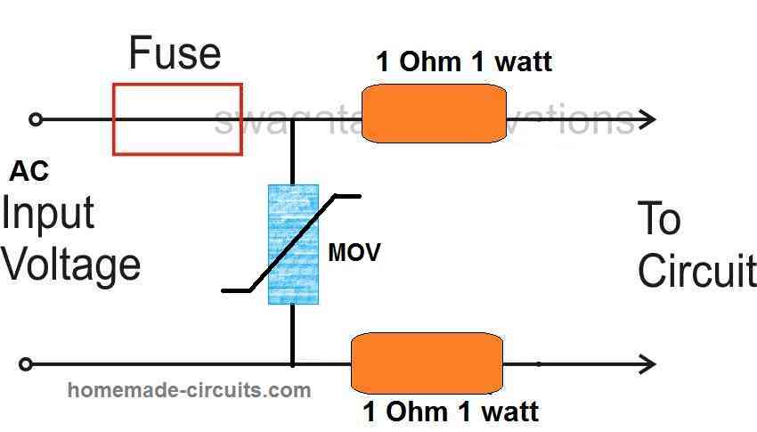
The diagram shown by you may not prove very effective, because it does not incorporate a resistor or any kind of barrier with the MOVs.
You may try the following circuit, introduce it at the entry point of the ballast circuit.
Hope it works:
Using an NTC and MOV
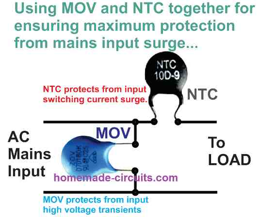
The following image shows how two different sudden high voltage suppressor devices could be tied up with the mains line for achieving a double edged safety.
The NTC here enables an initial switch ON current in rush protection by offering a higher resistance due to its initial lower temperature, but in the course of this action its temperature begins increasing and it begins allowing more current for the appliance until a normal working conditions achieved.
The MOV on the other hand complements the NTC output and makes sure that in case the NTC is unable to stop the up-surge onslaught correctly, it switches ON itself shorting the residual high transient content to ground and as a result establishing a safest possible supply for the connected load or the appliance.
Highly Recommended for you: 220 V AC Filter Circuit
Formulas for Calculating MOV and NTC Parameters
NTC (Negative Temperature Coefficient) Thermistor Formulas
Resistance-Temperature Relationship (NTC Thermistor)Using the Beta Parameter Equation:
R(T) = R0 * e(β * (1/T - 1/T0))
Where:
- R(T) = resistance at temperature T (in ohms, Ω)
- R0 = resistance at a reference temperature
- T0 (in ohms, Ω)
- β = material constant (in K)
- T = temperature in kelvins (K)
- T0 = reference temperature in kelvins (K), usually 298 K (25°C)
Using the Steinhart-Hart Equation (more accurate):
1/T = A + B * ln(R) + C * (ln(R))3
Where:
- T = temperature in kelvins (K)
- R = resistance at temperature T (in ohms, Ω)
- A, B, C = constants that depend on the specific thermistor.
Thermal Time Constant (NTC Thermistor)τ = (Cth * R) / P
Where:
- τ = thermal time constant (in seconds, s)
- Cth = thermal mass of the thermistor (in joules per degree Celsius, J/°C)
- R = resistance of the thermistor (in ohms, Ω)
- P = power dissipated by the thermistor (in watts, W)
Inrush Current Limiting (NTC Thermistor)I(t) = V / R(T(t))Where:
- I(t) = current at time t (in amperes, A)
- V = supply voltage (in volts, V)
- RT(t) = resistance of the thermistor at the temperature T(t) (in ohms, Ω)
Additional Formulas:
MOV:
Voltage-Resistance Relationship:
R(V) = (Vr2) / (V2 - Vr2) * Rmax
Energy Absorption:
E = 1/2 * C * Vmax2
Clamping Voltage:
Vclamp = Vr * (I / Irated)α
NTC Thermistor:
Beta Parameter Equation:
R(T) = R0 * e(β * (1/T - 1/T0))
Steinhart-Hart Equation:
1/T = A + B * ln(R) + C * (ln(R))3
Thermal Time Constant:
τ = (C_th * R) / P
Inrush Current Limiting:
I(t) = V / R(T(t))
RFI Line Filter and Surge Suppression Circuit
If you are looking for a mains AC line filter circuit having a combined protection against radio frequency interference (RFI) suppression, along with voltage surge control, then the following design could prove quite handy.
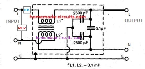
As we can see, the input side is protected with an NTC and MOV. The MOV grounds any instantaneous over voltage surge, while the NTC limits an over current surge.
The next stage constitutes an RFI line filter, comprising of a small ferrite transformer and a few capacitors.
The transformer arrests and blocks the passage of any incoming or outgoing RFI across the line, while the capacitor network reinforces the effect by grounding the residual high frequency content across the line.
The transformer is built over a small ferrite rod, having two identical winding wrapped one over the other, and one of the winding end connections swapped between the input/output Neutral line.


Questions & Answers
How does this differ than an AC powerline inlet filter?
Like TE dotcom 6amp:
2-1609109-1
I am actively searching for something that will stop reading light flickering while the window attached airconditioner runs
One outlet in room with two sockets
Top socket for air conditioner
Botton socket for non-surge power strip:
♦️spigen 100watt PD USB (20v 3a laptop),
♦️ 65waa pd usb (iphone),
♦️ reading lamp multibulb
It would be interesting to have an engineer evaluate Spigen’s claim about their “ArcStation Pro” feature reducing noise and ripple. Spigen is a brand designing quality pd usb chargers (and garage phone cases).
The above circuits are just for safety, where the MOV stops big voltage spikes like lightning and the NTC stops big sparks when turning things on, but they don’t clean the power. The TE filter is for cleaning high-frequency electric noise so your electronics don’t buzz or mess with each other.
Your lamp flickers because when the AC compressor turns on, it takes a huge amount of power instantly, making the voltage in your wall outlet drop for a split second. Neither the above circuits nor the TE filter can fix this because they can’t put dropped power back into the load. It’s the same for Spigen’s tech—it makes the DC power going into your phone very smooth, but it can’t fix the bad AC power coming from the wall. The easiest fix is to change your lamp bulb to a good, dimmable LED bulb because they have better parts inside that can handle that quick voltage drop without blinking!
Hi Swagatam,
I am trying to build a automatic Change over circuit. this circuit will be used for switching from Generator set to public mains supply, that will be made up of switching cct, Surge protector cct and filtering cct. indicator lights and alarm will be added. thank you.
Require TVs diode rating for 4 kV surge suppressor input voltage is 230 vAC.
Require solar flasher circuit for beacon light
Thanks for the Reply
I require circuit for solar opearted flasher, solar panel is 5v 150mA, LED 5mm Red 20mA ..8nos,Battery 3.6v Lithium 2600mAH with Dusk to Dawn switch
I have published the diagram at the end of the following post, please check it out:
https://www.homemade-circuits.com/rotating-beacon-led-simulator-circuit/
Sorry, I do not sell electronic components in this website, you can try other online stores, there are plenty of them.
I want only correct rating ,so that I can buy from market.
If we consider the diode breakdown voltage to be 400V, then the peak current of the diode must be 4000/400 = 10 amp.
You can search for 400V, 10 amp TVS diode for your application.
For the beacon light please provide more details regarding the voltage and load current…
We designed the PS for triggering solenoids for Pneumatic circuits and using 230 to 24 ac step transformer. But, used a fuse alone in the input side. But customer believes that we did consider for spikes and noises, We have taken earth connection through Transformer leg. Now, i am looking for a cheap surge protector and put that in series to transformer, take the surge protector pin out and connect to load, neutral and earth. 230v ac, SINGLE Phase. Is that correct. what else we need to consdier sir. Thank you.
Hi Krab, according to me, the following design is the cheapest and the best suitable for your application
https://www.homemade-circuits.com/wp-content/uploads/2021/01/MOV-NTC-compressed.jpg
thank you, but could you help me know how and which is connected to Phase , neutral and mainly in Ground Earth please. thanks once again. Why not add GDT for fast discharge . may i seek your view.
Can you please tell me what exactly are you trying to protect from voltage and current surge?
Surge protectors like, MOV, NTC, TVS, GDT all these are intended for protecting sensitive electronic circuits and devices, because electronic devices can burn even with a surge lasting only a few milliseconds.
However, in your case the load seems to be a solenoid mechanism and a transformer which are hugely rugged compared to electronic devices.
The surge current or voltage which may be capable of burning your transformer or solenoid circuit will also burn all other surge protection devices. So surge suppressors cannot be effective.
Because to burn a transformer or a solenoid the surge has to last a few seconds which is sufficient to burn any type of surge suppressor.
So a fuse is the best option that you have chosen to safeguard your inductive equipment.
If you are using an electronic circuit to control the pneumatic system, in that case the surge suppressors must be separately included within these electronic circuits, and you have to also make sure the solenoid coils include a parallel diode to control the generation of back EMFs.
Swagatham, i thank you for a detailed reply. This is a basic protection mechanism for the transformer powered solenoid valves energised through a bridge circuit. In fact, the normal expected failure mode at customer site, is huge inductive loads due to rotating components in their manufacturing site. So, whatever we supply them , need to take care of inductive loads . This is my view. A Basic protective mechanism. In addition, i had taken earth from the transformer body and given to customer location. Having said all these, the only fear is fluctuating inductive loads and some ground disturbances (??) less probability though. Hence, i wanted to request if GDT Will also help.
Thank you Krab,
That’s right. Your approach of using a GDT on the AC input side and grounding the transformer body is perfectly correct.
However an inductive load can get damaged due to sustained over voltage conditions also, which can be protected using a fuse, or a circuit breaker.
Hi Swagatam.
Can i use three MOV instead of one
one is for L to N
one is for L to E
and one is for N to E
I am asking you because some extension board company uses 3 MOV
Hi Sagar,
Yes you can do that!
Thank you for your reply I have one doubt. So should I use three of the same size of MOV?
Yes, all the 3 MOVs must be with the same specifications…
HI Swagatam.
How do we know if the MOV or NTC has been used up already and need to be replaced? It seems most surge suppressing devices in the market do not have indicator when the surge suppressing mechanism is already done and over? Any ideas on this? Thank you! You are awesome! 🙂
Thank you Kitt,
Unfortunately an LED indication might not be possible for indicating a burned or damaged MOV/NTC. The only way perhaps is through a visual identification. Examine the MOV/NTC for any visible signs of physical damage, such as cracks, burns, or discoloration. If you see any of these signs, it’s likely that the thermistors has been damaged and needs replacement.
Ok, thanks very much, Swagatam. Moreover, regarding MOVs, what is the recommended MOV to protect an inductive, resistive machine (with small 110v AC fan, 110V heater, with solenoid coli) that consumes 500Watts, 220volts? Is the Joule rating the required parameter? And the equipment will be used continuously for 5 years (8 hours off/ 16 hours on)? Thank you again! 🙂
You are welcome Kitt,
For a 110V load the MOV rating can be around 130 V RMS. 220V would be too high or the required protection.
Yes, while choosing a MOV for surge protection, the Joule rating is a vital factor to consider. An MOV’s Joule rating shows its ability to absorb energy. It specifies how much energy the MOV can withstand before degrading or failing.
Thanks Swagatam. May I know the MOV rating or label that you used in this example above? The image is not quite clear but the NTC is quite clear. Up to what voltage or current or load does your MOV/NTC combination example above protect?
Hi Kitt, sorry I cannot figure out the number printed on the MOV, it is too blurred. The load is not relevant to MOV but it is relevant to an NTC since NTC is in series with the load. You will have to select the NTC current as per the load current. The voltage of the MOV can be slightly higher than the peak voltage of the AC input supply, and current can be around 1 amp.
It was not the series connection of capacitor but the multiple capacitor connection in parallel.
Say as 1pf 1kv can hold a spike or surge of 6.28 Pico sec as it has 1 ohm impedance @ 159 M Hz.
Now in the same way if the spike is in nano sec an another suitable capacitor has to be introduce. Say as 1000pf will hold spike of 6.28 nano sec as it has 1 ohm impedance @ 0.159 M Hz
And so on for micro sec and milli sec
The 0.1uF capacitor is doing the same thing and in a more efficient way.
Hello sir,
Conceptually the circuit is clear, but I would like to know that the capacitors connected with the mains will also draw necessary power from mains.
Secondly why we are not using the series of capacitors with different values to cope up the different surges of different timings,say as in milli sec, micro sec , tens of millisec, tens of micro sec, etc.,,i.e. 10 pf 630 v , 100pf 400v and so on.
Please clarify my doubt.
Hello Dhananjay,
I guess you are referring to the last schematic. The capacitors have very low values so the consumption will be within 5 to 10mA only which is negligible. I am not sure where the series capacitors can be used, because series capacitors will block a lot current and prevent the load from working normally. By the way a capacitor will never block surge current, in fact it will pass all the surge current through it during the switch ON periods.
Hi Swagatam,
I am interested in building a device to plug into an unused 115 VAC outlet on a generator to protect from airborne EMP pulses. Plan to use a ferrite in series and MOV in parallel. This would not be inline with a load. Any suggestions?
Hi Dave, you can try the last circuit explained in the above article. It has a ferrite core based inductor and an MOV both
hello . thanks for sharing the simple home made circuits for voltage and current breakage. i need to know more in details for how NTC is going to stop high current. is it depending on the temperature ?? I am designing one small circuit to make safe home equipment’s like TV , Fridge in villages. as they start their pump , surge comes to main and other home equipment’s get damage. required simple and cost effective circuit for this purpose.
Hi, yes, NTC prevents current surge through temperature variations.
Initially, when power is switched ON the temperature of NTC is cooler which causes it resistance to be relatively higher. Due to this higher resistance NTC blocks the switch ON surge.
However, in the process, it warms up and the NTC temperature rises. When this happens it starts passing more current until the normal amount of current is allowed to pass.
Hi… thanks for revert and clearing me.
so will this NTC sense the surrounding temperature or temperature rise because of high current spike in wire ??
and if current spike comes , this NTC gets blow down or its just raise the resistance and when current is on normal again the resistance comes down !!
When NTC temperature is cooler it blocks current when higher it passes more current. As it passes more current it gets warmer. But this change in NTC temperature is quite slow, therefore sudden current changes and spikes cannot happen and in this way the NTC suppresses current surges. However if the temperature of the NTC rises too high then ultimately it will burn and causes an open circuit.
Dear Swagatam,
I live in South Africa and we are bombarded with daily blackouts. My underfloor heating is controlled by WiFi smart switches and I’ve already lost 2x smart switches due to voltage spikes when the power utility restores power. My smart switches are rated for 10ampsp and the max amp drawn from one of the underfloor heating panels is 4.6amps (1050w, 230v) so the smart switches are well within spec. My wall space is extremely limited, so commercially available surge protectors will not fit in the space.
I saw your circuit and was wondering if using a 2.5E 8A, 20mm disc thermistor coupled with a MOV 14mm RMS=230V 104J varistor will be adequite for the mentioned scenario?
Any advice will be appreciated
Thanks
Hi Casper,
yes I think the NTC/MOV combination should be able to tackle the switch-ON inrush problem. If it doesn’t then you can perhaps try a delay ON relay timer circuit.
Dear Sir,
I Need a circuit to attach to my Ham Radio Power supply(13.8 VDC) and a Battery Back up of (12 Volts DC) so that when the Mains go dead from Blackout the Circuit will automatically switch to the (12 Volt DC Battery) My radio is operated from (12 Volts DC Normally) From a power supply working from the Mains 220 VAC) the radio Draws about 20 Amperes on Transmit so the circuit would have to be able to handle at least (25 amperes @ 12 Volts DC) to be safe.
I Know they have commercial Units that do this Job, But I like Building my own Gear, I am a Ham Radio Operator.
Thank you and Namaste
Hi Bob,
You can try the following relay configuration for fulfilling your requirement:
HI Swagatam,
I’m at a revision of a Pinball machine. Either I replace the old bulky LineFilterAssembly or I take it apart and replace the components. This Filter is already 30 years old. It contains a Thermistor to limit the inrush current and a Varistor to protect from over voltage and it contains an EMI Filter. The whole LineFilterAssembly feeds a quite big transformer with 1 primary and 9 secondary. The highest secondary is 100V and the lowest is 9V. The whole machine is fused to 220V 5A T. Do you know a compact device who can handle the requirements? Would you restore the original LineFilterAssembly and replace the onboard components?
Hi Daniel,
The only EMI filter circuit that I know is the one shown at the end of the above article. You can probably try the last circuit from the above article by building the RFI filter using thick wires, may be 1mm thick.
Hai Swagatam,
I am working as a hardware engineer in one of the reputed company, and i am working on a filter.
Basically we install some electronic equipment’s in central railways and there there is 110VAC, which is regulated from railways 25000V. but when switching happens or power on off happens there is a high voltage surge and that surge is spoiling my LC filter as well, please suggest me a way to solve this issue.
input= 110VAC
surge = nearly 4000VAC
surge duration= 3-4 millisec
please suggest me a way forward to solve this issue.
Hi Roopesh, I think you must install powerful MOVs at the input side of the AC mains. One such example can be studied in the following article:
https://www.homemade-circuits.com/high-power-industrial-surge-suppressor/
Good morning sir.
Long time , please I have a question, may I use this circuit to apply it in my arduino circuit to protect my Arduino from EMF . because sometimes my Arduino hocked and stopped working at any time while in working because am using High voltage generator in the circuit.
Hi Kabir, the above circuits are meant for AC mains surge suppression, not for Arduino circuit. For Arduino circuits, you can feed the 12V to the Arduino through a 7812 IC and connect a 1000uF/25V capacitor right across the DC input pins of the Arduino. This will help you to get rid of any kind of interference from the high voltage generator.
Hi,
I would like to build an inductor (line reactor) as it was done in the patents used by Zero Surge, Surgex, BrickWall.
Could you walk us through how to build this type of inductor for overvoltage protection?
It is a 100mH air inductor in the case of Zero Surge but there are 2 inductors I believe in the case of Surgex which is even more efficient.
In the case of this circuit, the use of a ferrite would lead to a rapid saturation that is why you propose an iron core in your answers for the protection of overvoltages and not just as a common mode filter?
In your texts you write ferrites but I think it is rather an iron core (as you have answered to others) since ferrite indicates a mixture of metals… Otherwise, what type of ferrite do you suggest?
Hi, sorry I do not have the exact calculations for building the kind of surge suppressor that you are referring to, so it is difficult for me to suggest anything useful.
Yes iron core may work better for mains surge suppressor inductors since the frequency range of the input AC is within 50 and 60 Hz.