In the following post I have explained how to drive a relay by using an isolated method, or through an optocoupler device. We will learn three methods, first method is by connecting relay directly with the optocoupler output pins, second method is by using external PNP transistors, and third method is by using external NPN transistors. Any standard optocoupler such PC817, TIL111, or MCT2E can be used in the discussed circuit diagrams.
The question was asked by one of the interested members of this blog, Miss Vineetha.
Before studying the proposed design, let's first understand how an opto coupler works.
How an Opto-Coupler Works
An opto-coupler is a device which encapsules an LED and a photo-transistor inside a hermetically sealed, water proof, light proof package in the form of an 8 pin IC (resembling a 555 IC).
The LED is terminated over a couple of pin outs, while the three terminals of the photo-transistor is terminated over the other three assigned pin outs.
The idea of operating a relay with an optocoupler is simple, it's all about providing an input DC from the source which needs to be isolated to the LED pin outs via a limiting resistor (as we normally do with usual LEDs) and to switch the photo transistor in response to the applied input triggers.
The above action illuminates the internal LED whose light is detected by the photo-transistor causing it to conduct across its relevant pin outs.
The photo-transistor output is normally used for driving the preceding isolated stage, for example a relay driver stage.
Connecting Relay Directly with an Optocoupler
In the following circuit diagram we can see how a relay can be connected directly connected with the collector of the optocoupler's internal transistor.
Remember, although the above connection diagram looks simple and easy, you must ensure that the relay coil resistance is not below 300 ohms, otherwise the optocoupler may heat up and get destroyed.
So if you want to use the above configuration and connect the relay directly with the optocoupler, then you have to first measure the coil resistance of the relay and make sure it is higher than 300 ohm.
This is because, most optocouplers cannot handle more than 50 mA current as the load current, therefore the relay coil must have a relatively high resistance so that it does not pass more than 30 or 40 mA current.
The following concepts show how a relay driver can be configured with an optocoupler using transistors. As shown in the following circuit diagrams, the relay driver may consist a NPN transistor or a PNP transistor.
An external transistor is recommended in a situation where the relay coil resistance is low, below 300 ohms and the relay requires a higher amount of current above 50 mA.
Using PNP Transistor
As can be seen diagram below, a PNP relay driver is connected with the optocoupler. When it's a PNP transistor such as a BC557, the base terminal of the transistor is coupled with the collector terminal of the optocoupler's internal transistor, the emitter is connected with the positive line and the collector pin is configured with the relay.
The freewheeling diode associated with the relay safeguards the transistor from back EMF voltage spikes generated by the relay coil.
The resistor values are not critical, any resistor value between 4k7 and 22K can be used for the two resistors.
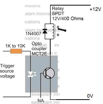
Using NPN Transistor
The next diagram below shows how to integrate an NPN relay driver stage with an optocoupler. If an NPN transistor such as a BC547 is used in the relay driver, the switching voltage is received from the emitter of the optocoupler's internal transistor.
Thus, the base of the BC547 NPN transistor can be seen connected with the emitter of the optocoupler transistor, emitter of the BC547 is connected with the ground line, and collector of the BC547 is configured with the relay. The diode has the same function as explained in the previous paragraph.
The resistor value is not critical, any value between 1K and 10K can be used.


Comments
Hi Bro!
I made this circuit (BC557) to drive an automotive relay. As this is to be used in an automotive application, the signal trigger voltage and also the relay driving voltage comes from the same battery source. Only the signal trigger is controlled so that it is turned on as required.
I am attaching a link to the changes that I made in this circuit diagram. I have made the ground common for both the trigger signal voltage and the driving battery voltage.
https://drive.google.com/file/d/0B7h83BRbOTR0N2NfUE1MWmtkb1k/view?usp=sharing
When I connected this circuit, the BC557 is conducting the full voltage without even the trigger signal volt wire connected. The relay I used was 50 ohm 30 Amps automotive relay. When this relay was connected it turned on without triggering the optocoupler.
When I connected a double coil relay with effective 100 ohms resistance, the relay did not turn on without the trigger, but when i connected the trigger signal wire then it turned on, but it does not turn back off even after removing the signal trigger wire.
Also the BC557 gets pretty hot within a few seconds. I tested all the components and they are all OK,
What am I doing wrong?
Also what changes should I make so that this circuit can be used with automotive relays and also noting that the driving source is same as the signal source?
Thanks for your help.
Regards,
Hi Bro, your circuit is absolutely correct, and there's no way the BC557 can conduct without a trigger unless:
1) your BC557 is faulty or connected the wrong way.
2) the opto is faulty or the input is leaking voltage to the opto LED.
confirm the second point by disconnecting the opto LED cathode from the ground line. If this corrects the issue then the problem could be due to a leakage voltage to the LED…check the trigger input to stop this leakage.
If the above does not solve the issue, then you may try disconnecting the opto transistor emitter and check the response…if this stops the relay driver conduction would indicate a faulty opto or an incorrectly connected opto.
By the way BC557 is not suitable fro driving a 50 ohm relay, you must use a 8550, or a 2n2907 or any similar 1 amp (C/E) PNP transistor for this.
sir. how can i drive a 12v relay with pc817 opto coupler with 2n2222 to isolate 220AC voltage from PIC MCU?
can you please help me?
…I think I got it….you can try the second circuit from the above article, the BC547 can be replaced with 2n2222
White dragon, can you please explain the link between 220V and the MCU, meaning how the 220V is related to the MCU circuit?
you can use triac or an ssr in place of a relay