In this article I have explained regarding how to connect and illuminate a few 5mm LEDs using a 3.7V Li-Ion cell, normally used in cell phones.
I keep receiving requests from the readers who seem confused with the connection details of 5mm LEds with a 3.7V Li-ion cell. The requests inspired me to write this post, hopefully it would answer the many related queries.
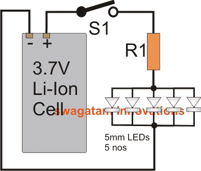
Using a Cellphone Li-ion Cell
Since standard 3.7V Li-Ion cells which are normally used in cell phones are rated at around 800 to 1100mAh, are quite capable of supporting a few 5mm LEDs, and would be able to keep them illuminated for quite sometime.
A normal 5mm white LED requires about 20mA current at 3.3V for getting illuminated optimally.
The circuit involved for illuminating 5mm LEds through a 3.7V Li-Ion cell is actually too simple, primarily because the parameters are closely matched with each other.
Here, connecting the 5mm LEDs in series wouldn't be feasible because the maximum volts from the cell is just 3.7V while even two LEDS in series would call for above 6V.
Therefore the only option left is putting them in parallel.
Ideally when parallel connections are involved, a series limiting resistor becomes imperative with each LED in the array. This helps ensure uniform light distribution or emission from the LEDs.
However it's not an absolute requirement, especially when the driving voltage is close to the forward voltage of the LEDs.
Also taking the simplicity factor into account, a single limiting resistor may be used in such cases and therefore here too we have eliminated individual resistors.
How to Connect the LEDs
The circuit diagram below shows a simple configuration comprising of a 3.7V Li-ion cell, 5nos 5mm LEDs and a limiting resistor R1. The procedure shows how simply a Li-ion cell may be used for illuminating 5mm LEDs for a reasonably long period of time.
Each LED is supposed to consume 20mA current, therefore 5nos would together consume around 100mA, therefore R1 may be calculated as follows:
The Formula
R = (Supply voltage - LEd forward voltage)/LED current
= (3.7 - 3.3)/100 = 0.4/0.1 = 4 ohms.
The required wattage would be 0.4 x 0.1 = 0.04W, so a 1/4 watt resistor would be more than enough.
Assuming the cell to be rated at 800mAH, with 5 LEDs, the approximate back up time available from the cell could be calculated using the following cross-multiplication.
800/100 = x/1100x = 800x = 800/100 = 8 hours ideally.
However practically you would find the above calculated back up time to be considerably less due to many inherent inefficiencies associated with the system or the circuit.
More LEDs can be added, if you are ready to compromise the backup time proportionately.


Comments
A single limiting resister can be used or not, when a 5V, 1A, 10400mAh output powerbank is used as a source.
Hi Swagatam,
Your blog and explaining technique is very good. I learnt a lot about powering LEDs. Thank you.
I need some help from you about my emergency light project which powered from 18650 x 2 batteries (3.7 v + 3.7v). I would like to glow 20 led (white bright) using parallel circuit. Please help.
Thank you Sunil, glad to know you liked my site.
Here’s the formula and calculations:
Assuming you want to illuminate 5mm LEDs high bright type LED with 20mA current each, 20 of them in parallel would consume 20 x 20 = 400mA or 0.4 Ampere.
The formula for calculating the current limiting resistor is:
R = (Supply voltage – LEd forward voltage)/LED current
R = (3.7 – 3.3) / 0.4 = 1 Ohm
wattage will be (3.7 – 3.3) x 0.4 = 0.16 watts or simply a 0.25 watt standard resistor could be used
for the emergency light circuit you could tr the following concept
https://www.homemade-circuits.com/how-to-make-efficient-led-emergency/
I think one drawback when you’re connecting LED in parallel is if one burn out the rest not emitting light.
In parallel connection even if one of the LEDs burn others will remain illuminated, however today the LED quality has improved a lot and they will not get damaged as long as the specifications are correctly maintained, regardless of whether they are connected in series or parallel.
Hi, the problem is caused due to their higher FWD voltage drop rating than the other LEDs in the group.
You must add resistors to each and every LED through proper calculation, as per the following formula:
R = Supply voltage – LED optimal FWD drop rating / LED's safe current rating
for example, for blue the above formula would go in the following way
R = 3.7 – 3.3 / 0.02 = 20 ohms
Hello, Swagatam. I like your blog very much.
But you are wrong, the resistor is not at 3.3V, but it is under 3.7 – 3.3 = 0.4V, and the power it manages is 0.4 x 0.1 = 0.04 W
Then, the resistor may be 1/8 W or less.
Regards.
Hi, you won't require a resistor for a bulb, resistor is required only for LED….still for better safety you can use a 1 ohm resistor in series
Hai iam have 3.7v nokia battery and also have 3v bulb iam light a bulb easily but please tell what problem cause if i not vonnect a ohm resistance and also tell what type v resistor i need to light a 3 v bulb using 3.7v battery please help me thank you
thank you Harry, yes that's a typographical error by me.
The wattage is always equal to potential difference across the resistor multiplied by the current flowing through it, that's simple Ohms law
I'll correct it soon
Resistors measured in Watts? What???
how to add auto charging and auto on/off LEDs when charger is plugged in
Hi, here are the details:
3.0-3.4VDC Forward Voltage
80mA Forward Current
30 degree viewing angle
16,000-20,000 MCD output
connect them in series, use a single 10 ohm resistors, 1/2 watt
Hi, who much voltage and current a 10 mm led require. I want to connect 4 10mm led to 12v bike battery in parallel. How much ohms resistance should I give. Whether parallel or series connection is optimum.