In this post I have explained the construction of a simple emergency charger pack using Nicket Cadmium (Ni-Cd) batteries for your cellphones and smart phones for emergency charging of your cellphone, so that next time you are never stuck on a highway with a full discharged dead cellphone battery.
Circuit Concept
It often happens, our cell phone goes into a low battery condition right in the middle of an important conversation, and even worse it happens while we are travelling or situated in some remote outdoor location where there's no charging facility available.
No matter what, this little pack will give your cell phone an immediate refill every time it tends to get flat outdoors.
We all know that at 3.7 V DC, a cell phone battery is considered to be fully charged.
For charging it at the above level a charging source needs to provide around 4 to 5 volts to the discharged cell phone battery.
Since here we are discussing an energy transfer from one battery to the other or rather from some power source to the cell phone, we need to have some sort of chargeable battery pack which would generate the required 4 volts and which could be used anytime for charging a flat cell phone simply by integrating the two together.
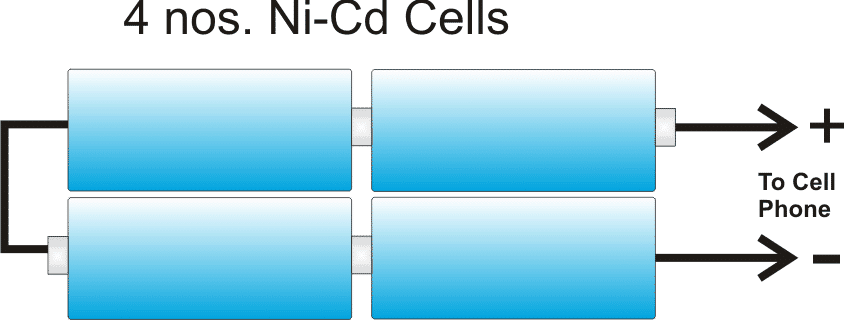
The above emergency battery pack can be very easily made by putting four Ni-Cd cells in series.
I have explained how to do it.
Materials you will Require
It's not difficult, you would require four 1.2V Ni-Cd AAA penlight cells, a four cell holder assembly and a 1 Ohm 1 watt resistor.
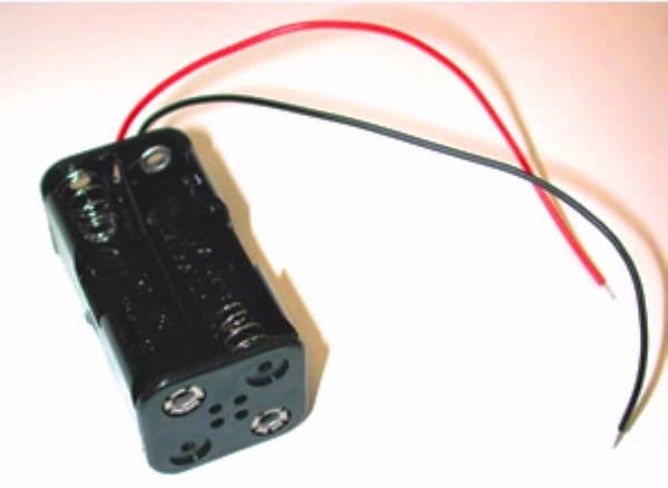
How to Build the Cellphone Battery Bank
The above holder would generate a voltage of about 4.8V at its wire terminals with four AAA 1.2 Ni-Cd attached to within the given slots correctly.
The 1 Ohm resistor can be connected at the center of the red wire by cutting the red wire at the center and bridging the resistor terminals such that it comes in series with the red wire. The resistor should covered under a plastic tubing or sleeving.
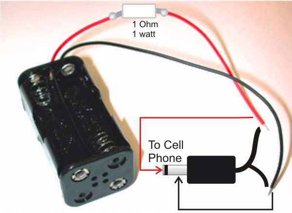
The red and the black wires of above assembly should be terminated with a suitable cell phone charger-pin so that it can be easily inserted into the cell phone charging socket whenever required.
Now I have explained how we can charge the above emergency battery pack at home.
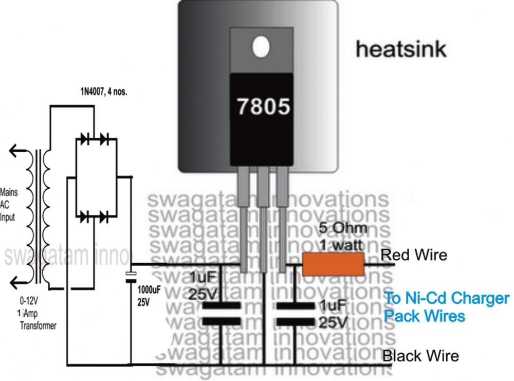
Ni-Cd cells can be charged safely for about 10 to 14 hours using a constant voltage charger at C/10 rate. The very useful 7805 voltage regulator IC can be used here for charging the Ni-Cd battery pack.
The following diagram shows a very simple Ni-Cd charger circuit which can be used for charging the above battery pack so that it remains in a standby position and can be taken outdoors in the form of an emergency cell phone charger unit.


Comments
hi sir, do you have schematic for an adaptor for digital camera? I lost the original adaptor of my BEAC digicam and I want to make a replacement particularly with -3.7V, 0V and +3.7V output to be powered from wall socket.
Please sir, if i use 1uf 25v Electrolytic capacitor, do i ignore the polarity?
And could you kindly state how i can identify the primary and secondary side of transformer. I have got all the components for this circuit but am having a problem identifying the primary side. The transformer comes with two sets of cord: at the foot where you screw, there are two black cords and two red at the top on the opposite side.
And is there a way of testing transformers?
Please i would appreciate urgent reply as i am very eager to build as my first DIY project.
for electrolytic capacitors the positive will connect with the positive line and negative with the negative line.
check the resistances of the respective windings…the one with higher value will be the primary for the mains input and the lower one will be the output.
Sir, any other values of resistors can be used? instead of 1ohm 1w & 5ohm 1w??
a 4.7ohm 1w can b used instead of 5? plz give any other values if so…
Rohith, other closer values can be tried but it should not be too large
Although not recommended you can connect them in series for charging, as parameters are not so critical with such low AH batteries.
the input can be 12V but at 500mA.
once fully charged it can revive a run-down 3.7V cell one time only.
why we can use the 1 ohm resister
for limiting the current to some good extent.
you may have to try bigger cells, AAA may not have the capacity of charging 1600mAH cell.
monitor the voltage of the adapter cells while it's charging the cell phone, if it drops quickly (below (3.9V) would confirm the cells inability…..
You can procure readymade 12V DC tube chokes which are designed for operating with 12V batteries, and power them through a 12V AC DC adapter, in this way you would be able to drive them with 220V AC suppy.
Yes it will still charge it,
use Ni-Cd type of cells.
AAA cells are rated at 800mAH