The post investigates a circuit which can be used for negating or neutralizing the everlasting harmful low frequency EMFs created from our mains power line in our homes. The idea was requested by one of the interested readers of this blog.
Technical Specifications
I'm trying to find a device or plans to build a device that will generate random EMF noise in the frequencies of 30 Hz - 100 Hz with an adjustable output of about 10 mG to 50 mG. The purpose is to disrupt the cellular oscillation caused by a constant 60 Hz high EMF in my house. Anyone have suggestions?
The debated harmful effects produced by the continues presence of various EMF content could range from regular headache attacks, uneasiness, insomnia, anemia, and even cancer.
It is said that if there could be a way to reveal the magnitude of man made EMF around us, we all would appear like swimming in a pool of EMF curd.
The advent of wireless technology has made our everyday lives so much dependent on it that now it looks impossible to detach ourselves from this harmful invisible enclosure.
The EMF surrounding us can be fundamentally classified into high frequency RF or radio waves and extremely low frequency EMF.
Both types are proved to have their own negative impacts on our health, however low frequency EMF being more easily reachable to us is regarded to be potentially much harmful than the RFs.
The main sources of these ELF EMFs could be our mains radiation from our domestic 50/60 Hz line through TV sets, mixer grinders, amplifiers, ovens etc.
As requested above an effective remedy to negate the influence of these radiations is to generate a counter ELF EMF having randomly changing frequency in the atmosphere near us or simply in homes.
The Design
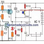
As shown in the below given home EMF protector or neutralizer circuit, we have a configuration which is capable of emitting different levels of low frequency EMFs in the surrounding in a random manner.
These emissions are likely to interact with the existing ELF EMFs producing a cancelling or neutralizing effect.
The circuit could be understood with the following points:
The IC 4060 is as usual configured as a free running oscillator.
The outputs from pin#1 to pin#7 produce frequencies varying with a factor of 2x, meaning a particular output could be consisting frequency 2x than the previous pinout or x/2 than the preceding pinout.
All these pinouts with individual frequency outputs are linked with respective common collector transistor configuration.
The bases of these transistors are in turn controlled by the sequential switching output from the IC 4017 which is clocked by the lowest frequency pinout of the IC 4060 itself.
Thus the 8 transistors are switched randomly such that they allow randomly selected frequencies to appear at the base of the power transistor TIP122.
The TIP122 responds to these random frequency switching and oscillates the connected inductor accordingly.
Neutralizing the ELF
The coil being subjected to these oscillations at high current levels start emitting the respective random ELF EMFs in the surrounding atmosphere for the intended neutralization effects over of the existing harmful mains radiation.
The power required for operating this proposed EMF neutralizer or protector circuit is 12V at 3 amps.
The inductor used could be a matter of experimentation. To begin with 500 turns of 30 SWG could be tried over a large laminated iron E-core block.
The 100k pot gives an option of setting the IC 4060 with different ranges of frequencies across all the outputs, as per individual preference or surrounding EMF level conditions.
Circuit Diagram


Comments
Hello swagatam.Isn’t using this circuit harmful to health? Doesn’t it pose a danger to people in the environment?
Thank you Mahdi,
This circuit is not dangerous for human health, in fact the microwaves from your mobile phone could be 100 times more dangerous than this circuit.
Hello swagatam, can you send a picture of the inductor sample that is placed in the circuit for a better understanding?
Hi Mahdi,
The inductor needs to be experimented a bit. You can initially try 500 turns of 26 SWG copper wire over a long iron bolt.
hi swagatam.Thank you for your explanation. What should be the length and diameter of the iron screw? For example, 3 inches long and 5 mm in diameter is good. How can I test its performance after building the circuit?
Hi Mahdi, Any iron bolt which can accommodate 500 turns of 28 SWG or 30 SWG copper wire will do the job.
Unfortunately there’s no quick way to test the health benefit results from this equipment.
Hello Swagatam , thank you for the good content you share.
IC 4060 pin number 2 Where does it connect to circuit?
Thank you Mahdi, The pin#2 is not used because it has a very low frequency, so this pinout has been eliminated because it is not suitable for the application.
👏👏👏👏❤️
Hi Swagatam
Thanking you for creating such great site which is immensely helpful.
Now, pl. Help me to resolve the replacement of transistors ( CSGS 401S) in the PCB of Aquaguard Water Purifier. These are the switching transistors for UV lamp driving 12v across a relay
Dear Swagatam,
I”ll definitely let you know the RELAY Sp. later on. You just made me your amazing fan. Lot of thanks
Thank you Subrata, I appreciate your thoughts, keep up the good work!
Thank you Subrata,
I tried searching the transistor datasheet online but I could not find any genuine information about it.
Can you tell me what is the precise function of the transistor in your circuit? Is it used as a relay driver transistor?
If yes then please provide the relay specifications also….
hello, this is pankaj,
can you p help me with one circuit with ELF DETECTOR AND NEUTRALIZER. it should have LED so that one can see visually the elf wave and once its neutralises the bulb should get off.
pl help for this . i am planning for its large quantity. my mail id info.upgradejr@gmail.com
Hello, sorry that’s almost impossible to do, because the above circuit is itself generating some random EMF which is interacting with the existing EMF to neutralize it, so the LED will not be able to distinguish the transmitting EMF from the external EMF.
Also, the external EMF cannot be be neutralized permanently, it will be a continuous process.
Good even8ng sir how are you khalid here i have built the emf circuit but when i connect the 12v sullpy to the circuit the supply bevomes zero after few sends and the make some sound tik tik and supply becomes zero the supply i am using is 12v dc it is ready made like smps i found old .for this problem i checked all 547 trs it was ok but i teplaced new and checke tip122 it was ok but i put new i replaced ic 4060 i have another bit the problrm not salved i make all connections new and cleaned the ocb with petrol and topth brush i connections very carefully and still same problem the 12v supply becomes zero after few seconds so what is your suggestion the inducter im using is 0 12v 220 transformer now only remaing 4017 ic and inducter but other all things i checked not salved the problem so please give some suggestion yours reply will be valuable and i know you have solutions i will be waiting for your reply thanyou very much i will be back. Take care.
Hi Khalid, please check the stages step wise. First check whether your IC 4060 is oscillating or not, next remove the inductor and check the response again. If the issue stops then the inductor turns could be the problem. Finally, use a 0-12V transformer and attach the 0-12V winding in place of the inductor, and also try fixing the frequency to 0.5 Hz around pin3 of 4060
Hello sir how are you khalid here i built the circuit but the 1uf capacitor negative where should be connect because i built the circuit and connected all the points corrctly but when i connect the supply voltage drops same like short circuit so i guess the capacitor may be problem i am ising 1uf 50v and as an inductor i am trying a transformer 0 24 220 i removed some tonnes from secondary on 24v side is this ok plese reply for capacitor negative also i am waiting for the reply thankyou very much i will be with the result.
Hello khalid, the 1uF capacitor should be a non-polar capacitor. Before connecting pin3 of 4060 with pin14 of 4017, you must first confirm whether the IC 4060 is oscillating or not…you can use 0-24V side of the transformer for the inductor.
Hai sir khalid here how you are doing today and you may be fine my prays with you . I have 1 question if i want to add an led 1red for before neutralise and 1green for after neutralize to know the conditions so where the led legs to connected means to which point please. I made this circuit but i want to add leds so this remaining after this i will send picture how its working to show you because are my master thanks wsiting for reply.
Thank you khalid, unfortunately there’s no easy way to detect the neutralization results with LEDs…it may require a highly complex circuitry for such detection
Sir, any tools or software is available to analysis the emf radiation. Please help me
Raj, here’s one idea that might work:
https://www.homemade-circuits.com/2014/07/thunder-lightning-detector-circuit.html
It will work only with a battery, not with DC adapter, and make sure to attach its negative line with an “earthing” such as your bathroom tap
Sir, thank you for your valuable reply
is there any possibility to increase the range?
Thanks Raj, yes it may be possible by appropriately increasing the current in the coil
Sir , i have one doubt
In ic 4060 , why pin #2 is not connected ?
Please reply
Raj, each pin in the sequence is 2 times faster in frequency than the previous pin. Pin#3 is slowest, pin#2 is 2 times faster than pin#3, pin#1 is 2 times faster than pin#2…and so on.
Suppose If we select pin#3 as 1 pulse per second then pin#2 will be 2 pulse per second, which is quite slow or less in frequency and may not be useful for the required purpose, therefore I have eliminated pin#2.
Sir, i am doing this project.
Any videos for making the circuit
Please upload because it is very helpful for my understanding
Deva, I do not have any videos, but I can guarantee the circuit will work 100%…. however it is not verified whether it can actually help to neutralize the EMF radiations or not, because there’s no way to check this.
Sir, what is the range of neutralizer (terms of square feet)
Raj, it will depend on the frequency and the inductor value, but in general the range will be within 100 sq ft.
hello sir, i got all the component that i need to make this circuit, but i don’t know about the inductor. could you please tell me the detail for that inductor? “200 turns magnet wire over an iron bolt”. What size of magnet wire and iron bolt?
Hi Rama, The coil is actually a random selection, because we do not exactly know what frequencies need to be neutralized, and it could also depends on the frequency adjusted by the pot.
Initially you can try a small 12/220V/500ma transformer, and connect the 0-12V side with the transistor.
And make sure to adjust the pot such that pin#3 of IC 4060 generates a frequency of not less than 2Hz.
THe 220V side can be used as an antenna for propagating the waves.
thank you sir, i will try it
I am planning to build the circuit, however it is difficult to find the inductor here. Is there some option online where I can buy one?
Thanks Neeraj, for measuring EMF, perhaps you can use a high power amplifier and connect an antenna at its input using a 5 feet flexible wire and connect the output of the amp with a AC voltmeter…this will let you know how much stray EMF may be present in the area…
Thank you sir for the valuable input, I will let know once the circuit is complete.
Also additionally it would helpful to know if you know of a way to measure EMF levels at home using any android app.
you can build it by winding 200 turns magnet wire over an iron bolt
Sir how can we understand whether this circuit is working or not ? How can it be felt to have the surrounding emf got reduced ?
you may be able to see improvements in your sleeping pattern (more clamness while you go to sleep), no dreams), lower stress levels, less tiredness etc.
2 or 3 times maximum with a fully charged battery