A Taser circuit also known as Stun Gun circuit is one non-lethal electric shock producing unit used to paralyze a person for a time being without causing any severe damage or injury. It is a very useful device, especially to immobilize an attacker.
Using and making of stun gun is restricted in most of the countries.
However, in the United States of America, some states allow the use of stun guns.
A stun gun is available in variety of styles like lipstick stun guns, cellphone stun guns, stun batons, police force stun guns, pink ribbon stun guns and disguised stun guns.
Warning: The circuits I have explained below are designed to generate high voltages in the range of many kilo-volts, which may be capable of delivering a painful shock. Appropriate caution is recommended while building these projects.
How it works?
Please read the following instruction before constructing:
Also known as a Taser gun this gadget generates substantial voltage pulses which can disrupt muscle tissues and neurological system, forcing any individual who touches it in a condition of mental bewilderment.
The unit may be used against attacking beasts or dangerous intruders.
Be aware that, this gadget could be prohibited in your country.
This gadget may be extremely dangerous on folks having cardiac issues, who may be using external electronic apparatus (like peacemakers), since it can deliver quite a bit of RF interference.
Don't attempt reckless behavior using this gadget, it is far from a plaything.
A Taser functions like two-stage voltage converter. In the first stage, the high frequency switching transformer increases the battery voltage to several kV to charge the capacitor. After the capacitor is charged, it powers the second transformer by increasing the voltage to 10 – 50kV (approx.) with the repetition rate of 5-40 Hz (approx.).
Taser Types
There are basic types of Taser: Multiplier, Thyristor and spark gap. Multiplier Taser is made of one transformer having voltage of higher output and it runs on DC voltage.
This type of Taser also has high-voltage capacitors and diodes and it is for the capacitors that multiplier Taser makes loud sound.
The Thyristor type is the most efficient one. Here the voltage of the capacitor is not high (250 – 500 V approx.) and it functions with the aid two main components: resistive divider (neon lamp) and diac.
The spark gap guns on the other hand is the most cheapest and ineffective stun gun. As the name implies, it has spark gap to function and the voltage of the battery is charged with transistor converter.
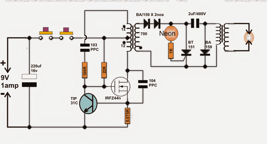
Design#1: How I made my Taser
Of the three types of Tasers, I chose to go ahead with the Thyristor because of its effectiveness. I used MOSFET (Metal–Oxide–Semiconductor Field-Effect Transistor) to build the voltage converter. The main reason to use MOSFET is purely from the point of efficiency.
In a push-pull converter which is generally used in stun guns, the level reaches around 20% whereas in MOSFET the converter gives efficiency as much as 75% with the working frequency of 80-120 kHz.
I then used a gate thyristor for the second switch along with four neon glow lamps with the ignition voltage of 95V and the pulse repetition rate of 30 – 50 Hz.
Transformer Specifications
For inverter transformer, I preferred to use EE core based transformer keeping the middle column cross-section of 20 – 25 mm2.
The air gap of 0.5mm thickness is place in the mid column. The primary polarity is set to 2x12 turns of the diameter of the wire (0.4mm) while the secondary polarity is set to 700 turns of wire (0.1mm).
The secondary polarity is wounded in multiple isolated layers. The reason to isolate the layers is to avoid breaking the wire enamel under high voltage. There are two electrodes in a Taser gun. They look like a dart and are connected to the main unit with a conductive wire.
Battery Specifications
One can power a stun gun with either six 1.5 V cells or seven 1.2 V cells.
The best option is to have two cells or Li-pol or Li-ion connecting the series. It should be noted that this stun gun may draw current upto 1.5 amps when switched ON, which means ordinary batteries might not work efficiently, and drain out quickly.
Written and Submitted By: Dhrubajyoti Biswas
Circuit Diagram
Design#2: Using IC 555
The proposed stun gun circuit description may be understood as follows:
The 555 IC is connected as a astable to generate rectangular waves with variable frequency and duty cycle (see the potentiometers and diode).
This signal is fed to a IRF840 Mosfet (not necessary to incorporate totem transistor network, as frequency would be reduced, nonetheless the IC has adequate current potential to swiftly charge/discharge the gate).
As an alternative for the mosfet a bipolar transistor works extremely well (add a 100 ohm resistor between 555 and base of the transistor).
Proper BJT could be BU406, but additionally scaled-down BJT may be ok, take into account that it should be able to cope with a minimum of 2A nonstop.
The inductive boost snubber isn't called for since the electrical power is lower which is practically completely adsorbed to charge the tank capacitor, furthermore because this gadget is battery powered we don't wish to disperse the power on a resistor, yet we need to produce the sparks.
With a snubbing system you are going to encounter decreased firing levels. Utilize A PUSHBUTTON SWITCH FOR Protection
Building the Transformer for the stun gun circuit:
This could be the actual tedious aspect. Because it in retailers we have to construct these. Components essential: enamel copper wire (0.20 mm or 0.125 mm), ferrite rod, LDPE sheets (0.25 mm).
Coat the ferrite rod with a application of ldpe (polyethylene, as a substitute utilize electric insulating tape) and stick it (or tape it) Position 200-250 winding on the ldpe (a lot more winding would do in case the rod is more than 1'), an additional ldpe application, yet another 200-250 winding and so forth to eventually have 5-6 tiers (approx 1000-1400 turns nonetheless supplementary turns wouldn't negatively affect the functionality), then again be cautious for internal arcing that could destroy it.
Insulate it once more and set the primary winding, 15-20 turns of 1mm wire would be simply fine, an excessive amount of winding will probably lead to lesser current and reduced spike in T2 secondary on account of decreased rise period, and too few is not going to saturate the core.
Go for MKP capacitors since they have minimal ESR and ESL (these are popular in tesla coils as mmc capacitors).
The Spark Gap
The spark opening could be straightforwardly a pair of crossed (although not touching) 1 mm spaced wires. It works like a voltage regulated switch, firing when the voltage is just nice to ionize the air between them (transforming it to plasma with smaller resistance).
Remember that it could be sensible do put it into a compact plastic box and stuff with oil allowing bubbles away don't employ motor oil or frying oil, rather organic mineral oil which includes zero water inside.
Circuit Diagram
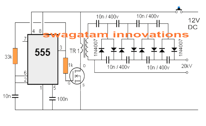
Parts List
- Resistors 1/4 watt 5% CFR
- 33k - 1no
- 1k - 1no
- Capacitors
- 0.01uF ceramic - 1no
- 0.1uF ceramic - 1no
- 0.01uF/400V metallized polyester - 8nos
- diodes 1N4007 - 8nos
- Mosfet - any N-channel general purpose mosfet with minimum 1 amp current (ID)
- IC - IC 555
- Transformer - as explained in the article


Comments
What is output current and voltage rating of this circuit..plzzzz reply???
the voltage should be from 6V to 12V, and the current around 2 amps
thanks for updating the info, appreciate it very much!
Hi Mr.Swagatam.
How many volt is the output and how is the Transformer T2?, can I use TV FBT/flyback transformer?,maybe by seperated between primary n secondary?,or new own primary winding?,how many turn?,thanks in advanced.
Hi ronald, yes you can use a TV flyback transformer for TR2…i am not sure about the winding details, may be you can try the existing primary of the FBT and check the response.
the output will depend o the FBT specs.