Contact mics can be used to sense unusual sounds when attached to various surfaces.It also Produce sound when voltage is applied to it.With the help of a basic Pre-amp circuit it can also be used to Electrify an Acoustic Guitar, where amplification is a must.
Written and Submitted by: Ajay Dusa
Piezoelectric Disc as the Sensor
A piezoelectric disk generates a voltage when deformed. Piezo elements come in handy when you need to detect vibration or a knock. You can use these for tap or knock sensors pretty easily by reading the voltage on the output. They can also be used for a very small audio transducer such as a Buzzer.
The trick is the preamp – a basic circuit used to match the piezo’s signal.
The resulting piezo/preamp combo can be used for electrifying an acoustic guitar.
Circuit Diagram
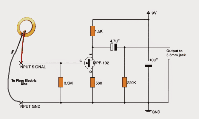
Circuit Operation
The battery supplies +9 volts which is connected to the source of the JFET device, MPF-102. This voltage is connected to the source through source resistor 1.5K.
One terminal of this amplifier is common to both the input and output signals. This terminal is the JFET drain terminal.
For this reason, we sometimes call this amplifier circuit a "common drain circuit”.The Drain resistor 220k is connected to the source to the battery's ground terminal.
Using MPF-120
The main Element used in the circuit is the MPF-102 Transistor.
Under no-signal conditions, bias voltage causes the JFET source to draw a very small current. This current sets the source voltage at a point halfway between the Supply and ground.
This is the recommended bias setting for most small-signal or analog audio amplifiers.It allows the maximum signal before distortion.
The signal enters the amplifier through gate resistor 3.3M. The voltage drop across 3.3M is the input signal at the JFET gate. This signal is an AC voltage.
How JFET Works
The signal enters JFET,which is a amplifying device.The difference between the source and the gate sets the voltage drop across resistor 560 Ω.
Normally, the bias voltage across resistor 560 Ω holds the JFET channel at a medium resistance value. The bias voltage is a DC voltage. When we apply a signal, the input signal varies the negative bias voltage across resistor 560 Ω.
The varying gate signal causes the JFET's to vary. For this reason, more or less current passes through the JFET.
The source resistor 1.5K converts the current variations to voltage variations. Since the input signal controls the channel width.That is, a small signal controls a large signal. In our case, the JFET gate voltage controls the JFET source current. This result’s in Amplification.
The output signal appears between the Source and ground. Capacitor 4.7uF blocks the DC voltages in the circuit, but passes the amplified AC signal.
The gate is more negative than the ground terminal. Now the output comes out across the Source and ground. But we've connected the Source to Supply.
Then the Source is more positive than the ground terminal. With the gate negative and the Source positive, This output signal exits the amplifier through capacitor 4.7uF and appears across resistor 220k. This Capacitor blocks DC and passes only.
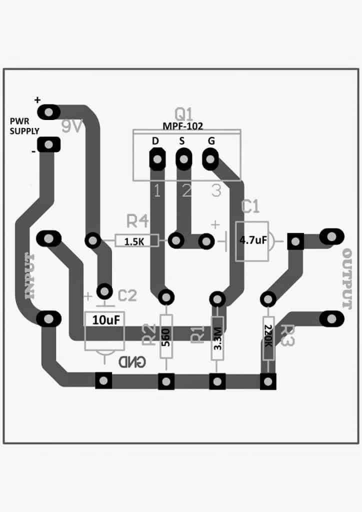
PCB Design for the above explained DIY contact MIC circuit
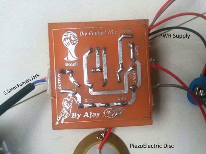
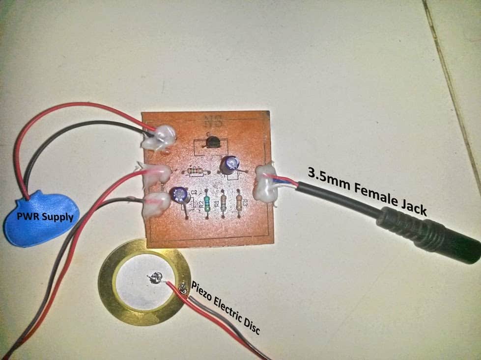
Following are the images of the DIY contact mic prototype, built and submitted by Mr.Ajay Dusa



Questions & Answers
Can you post a video how does it sounds?
ese preamplificador cual es la potencia de salida
This looks like it might be just what I’m looking for, to finish off an Arduino Shield I’m working on. What modifications, if any, would be recommended to get this to work at 3.3V? (There’s also a 5V bus, but the output will need to be 3.3V.)
Thanks, I guess the circuit should work with a 3.3 V supply if the FET is replaced with a 5 V one.
How might I identify a 5v JFET? I don’t see any online that have such a low rating. The lowest “Maximum Gate Source Voltage” I see is -25v. Thank you!
The 5V actually refers to the VGS or the gate voltage of the FET through which it can operate optimally. Normally FETs require 9V to 20V gate voltage for optimal performance. You can search for “5V FET” you may find many relevant results.
Thank you for your reply!
I haven’t yet. I still have to work on programming the Shield before I can assemble the mic system….
Hi Bob, did you build this mod? How did it work? I’m also interesting in powering one of these pre-amps with 3.3v from an arduino/teensy. Thanks!
Hi I am having query. Can i connect its out put to AUX port at my amplifier.
Yes, …..if it is an AUX Input
Can I use any other transistor instead of MPF 102
You can use Depletion mode JFET in its place
Thank you for the circuit, which I’ve built and tested on a proto-board with success! I’m chuffed as this is my second circuit build and a little step up from my ‘fuzz for a fiver’ project. It was exciting and nervewracking to put the battery on. Capcitors, polarity… Check!
I ran the audio into a little mini mixer because I didn’t know how many decibels it was going fire out of my headphones and this allowed me to tentively turn up the volume. There’s a little bit of hum when turned up loud.
I quite like the idea of sticking the circuit in a box with springs and things to rattle, but would also like to have two piezos for 2 placements and possibly 2 sizes of piezo if there is a tone difference. This would give me a stereo option (2 mono jacks into left and right). I’m sure there’s a more elegant way of doing it, but I’m thinking two circuits for each piezo and splicing onto a 9v battery connector to power the 2 circuits off of one 9v battery.
Thank you updating your results, appreciate it very much! Yes you can create a couple of those circuits to generate a stereo output. You can use the same 9V supply for both the circuits.
Thank for the help Swagatam – this website is a brilliant resource and your explanations help massively 🙂
My pleasure Clive, Glad you found the website useful.
Hi I am looking for a simple Fet compressor , that I can plug into the insert sockets on my recording desk , I would like to say biuld 12 of them in a box and put them into the insert on each chanel and set then so we can make better live recordings , then perhaps in the future add sustain ,attack ,decay ,release ,ratio . but at first just a simple agc
Cheers Geoff
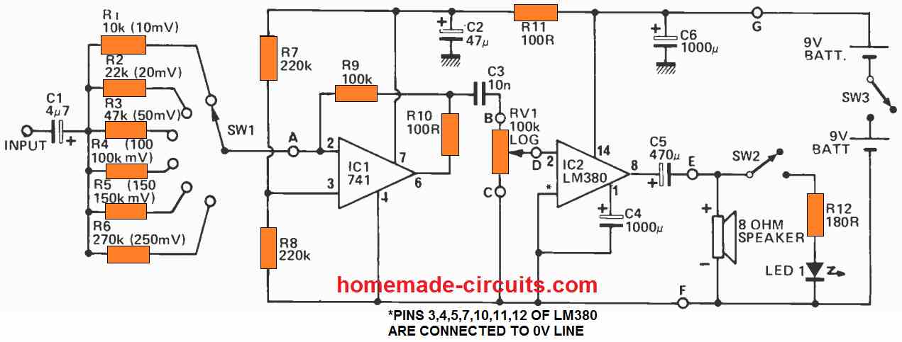
Hi, you can probably try the following design. Although it is a BJT based compressor circuit, you can replace the BJT with an FET and check how it responds.
The 1N34 diodes could be perhaps replaced with 1N4148 diodes, however I am not entirely sure about it.
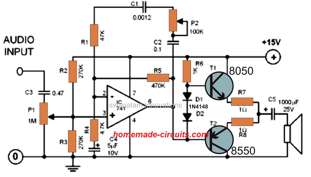
You can also try the following IC based circuit for improved results:
What a wonderful resource, many thanks for you passion.
I am building the contact MIC preamp circuit to run a bridge piezo pickup,
I would like to put his in a metal box to potentially shield RFI and EMF interference.
Is this a good idea and if so, what would I ground the box to?
Kind regards
Ivan Parke
Thank you, and Glad you found the site helpful.
Using a metal box sounds good. The negative supply rail of the circuit can be grounded with the metal box for RF shielding.
Hello I just have some questions regarding this circuit. I have a piezo pickup for my acoustic guitar installed inside of my guitar and it also has 3 piezo in the back. I already tried the circuit and tried to use in my pickup, the preamp tone was good but my problem is instead of amplifying the volume of my pickup, the volume it produce is just about the same before i use the preamp. Do you have any suggestions so that i can maximize the volume it produce for my pickup? I also want to mention that I only use 3.0M ohm resistor instead of the 3.3M ohm.
Hi, the above design is a preamplifier, so it won’t generate an amplified output for the guitar.
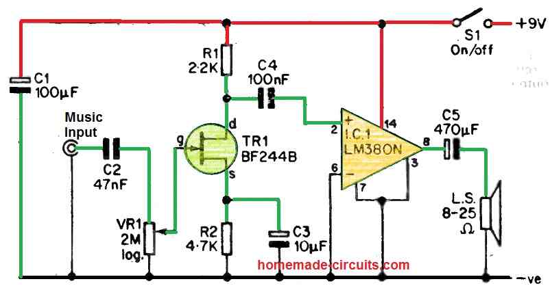
In order to amplify, you can simply hook up the output from the above circuit to a power amplifier circuit.
Or you an simply eliminate the above design and hookk up the following circuit with your existing piezo outputs:
More amplifier options can found in the following article:
https://www.homemade-circuits.com/mini-audio-amplifier-circuits/
https://www.homemade-circuits.com/simple-10-watt-amplifier-circuits-explained/
Hello, I would like to add volume and tones controls (bass and treble) to this pre-amp circuit.
I’m building a classic guitar with 6 piezo pick-up, one for each string. Do you have a circuit diagram to add the controls to your pre-amp? Thanks in advance. Greetings
Hi, sure, you can try one of the circuits explained in the following article and add it to the output of the above circuit..:
https://www.homemade-circuits.com/simple-tone-control-circuits/
hi, thank you.Can I try the first one listed in the page you suggested me? It doesn’t need power supply and it’s very simple to build. Thanks a lot. Greetings
Yes you can try the first design and add it between the output jack and the external amplifier…