The post presents a cheap cellphone remote controlled water pump circuit which allows farmers (user) to switch ON their field water pump without practically visiting the spot, thus saving precious time and energy for the individual. The idea was requested by one of the dedicated members of this blog.
Inexpensive Cellphone Water Pump Starter
This is with reference to the comment of Mr. Raj Mukherji, January 16, 2013. He explained it very well. In addition, farmer suffered from infrequent power cut (6 hrs power supply in aprox. 10 irregular blocks) so it is very irritating for a person.
I want to apply this type of circuit for three phase induction motor in my village and it will be made for my village also. I humbly request you to develop the circuit for the welfare of our poor villagers. They are not able to purchase it from market.
I will be grateful to you.
The Design
To make this simple cell phone controlled water pump starter circuit for the farmers, you will require the following ingredients:
1) A cheap cell phone (such as a NOKIA1280) which has an "assign tone" facility, meaning a cellphone which can save a specific ringtone for a selected number and enable muting the remaining numbers, in simple words the cellphone will "ring" only to the selected (preferred) number and stay silent for other numbers regardless whether or not its from the phonebook or a wrong number.
The above unit will be used as the modem and will remain permanently attached with the control circuit.
2) A sound activated circuit such as a typical clap switch circuit
and a 3) monostable 555 timer circuit.
UPDATE:
Looking for an advanced solution? Read more below:
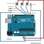
Advanced Microprocessor Based GSM Water Pump Controller
I have explained how this interesting cellphone controlled water pump circuit can be implemented for the farmers, as described below:
In a few of my earlier posts I have comprehensively explained regarding how any load across any part of the world can be actuated using a cheap cellphone remote control circuit, you can learn more about these from the following links:
Cellphone Display Light Triggered Remote Control Circuit
Vibrating Cell Phone Remote Control Circuit
Controlling Motor with a Cell Phone - Circuit Diagram Explained
Making a Cell Phone Controlled Remote Bell Circuit
Cell Phone Controlled Door Lock Circuit
Build a Homemade GSM Car Security System
In the above designs the relay is seen to be activated using the attached modem cell phone's ringtone through its headphone socket.
Using a MIC Sensor
In the present pump controller design we implement the same but through a mic sensor which is utilized to sense the ringtone of the modem without making any physical contact with the modem cell phone.
The idea can be understood from the following diagram and the explanations:
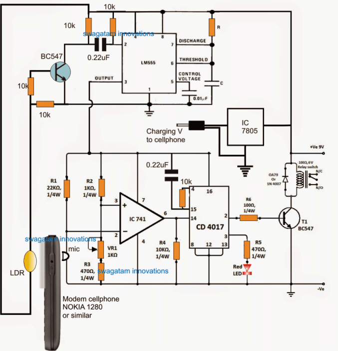
The lower section of the circuit incorporating the IC 741 and the IC 4017 forms a simple sound activated relay circuit, which toggles the connected relay alternately ON and OFF in response to the sound signals received on the MIC. Basically this circuit is used in clap switch circuits for toggling the relay with clap sounds.
For the proposed application the sound is produced from the cellphone when the user calls the shown attached cellphone from his home or some distant location for operating the relay and the water pump.
The idea looks pretty simple until here, however the mic could be triggered even with a false sound trigger generated externally in the filed, for example by an airplane sound flying close by or a vehicle such as a tractor engine sound etc.
Using Monostable Circuit
To eliminate this issue and make the circuit foolproof, a IC 555 monostable is additionally used with the lower section.
The monostable is designed to trigger from the display light of the cellphone whenever a call is received.
Therefore now it becomes a double edged sensing device which will not trigger unless the light from the modem, as well as the ringtone sound are produced together.
Whenever a call is made on the modem. The display lights up first and hits the LDR, the LDR resistance goes low triggering the BC547. The BC547 conducts and pulls the pin#2 of the 555 IC low which in turn enables its pin#3 to go high.
The pin#3 output from the IC 555 powers the lower section, which now becomes ready for the subsequent sound detection.
Following the display illumination, the ringtone from the modem sounds, and triggers the relay and switches ON the connected water pump.
The monostable timer remains switched ON for a stipulated length of time, determined by the IC 555's R and C component values, after which its pin#3 goes low deactivating the entire circuit and the pump motor.
However in the meantime if the user wants to switch OFF the pump he can do so by calling the modem for the second time within the time frame of the monostable activation.
Although the discussed cellphone operated water pump circuit for aiding poor farmers looks very simple, foolproof and cheap, it has its own drawbacks.
The farmer is never able to know whether the pump was actually started or not, because there's no reverse acknowledgement from the modem to the user regarding this.
The above issue can be though rectified by adding a momentarily activated siren, which will produce a loud ear piercing sound as soon as the pump is initiated or the water flow is detected.
The siren sound should be loud enough to be heard over a radial distance of approximately a kilometer. This acknowledgement method will work only if the farmer's home is within the above mentioned distance from the pump motor.
Advantages
The advantages of the above design are:
The above circuit will not consume your modem's talk time unlike the DTMF based systems which eats-up the cell phone talktime while it's in use for the required function.
The circuit does not utilize complex parts or obsolete parts rather works with ordinary parts such as IC 741, IC 555, IC 4017.
The circuit does not interfrere with the modem in any manner rather works without making any physical contact with the associated modem.
The circuit is cheap and well suited for the proposed application and for the poor farmers.


Comments
Water pump operation by using cell phone in these project we can physical contact with the pump or not
Please explain your question properly, I cannot understand it?
Hai sir,
Few doubts in transistor.
Battery 6v 4.5Ah
2 led in series 6v 200ma
I tried this using PNP transistor for emergency lamp purpose.
1st i use TIP127 the led glows dim and i measure Ampere it shows (90ma)
2nd i use BD140 the led glows brighter & perfect and i measure ampere it shows (190ma)
my doubt is BD140 is 1.5A ratings it glowing led very well.
TIP127 is 5A ratings but its not glowing well.
what is the reason sir.
and pls tell how to choose transistor as per load.
Hi Kesava, the reason may be due to a duplicate or faulty TIP127, or may be you have connected it wrongly. TIP127 is a Darlinfgton with a much higher gain than BD140 so it must produce much brighter illumination….try replacing the transistor.
Hi Kesava,
which circuit are you referring to? Please post your question under the same article so that I can view the schematic quickly and suggest
Few doubts in this project:GSM Pump Motor Controller Circuit using Arduino
1st code i tried its working well.
2nd code i tried works but not send any ack.
In comment section Anupam Dasgupta code i tried.
But it shows error
stray’\342′ in program
Pls guide me sir.
sorry kesava, my arduino coding knowledge is not good, so cannot help you in this regards.
Sir ..this circuit can you mount breadboard
hiii sir where i connect the motor???????
please tell what exactly cd should i use so as for opamp to respond to connected mic
the prefix can be ignored…only the number is important.
I tried to use cd 4017BE h9623 but it does not respond to opamp when i connect with mic only led light up
You must follow the instructions which I suggested in the previous comment….you'll need to confirm each stage separately
SIR WHAT DECADE COUNTER SHOULD I USE AND OPAMP
any 741 IC and any IC 4017 will work, the number is only important…the initial prefix is not.
and also when i connect the stepper motor it run directly without using sound from the ring tones and i use hand phone mic is it good to use it?,thanks sir
Go stagewise as suggested above…don't connect any load until all the stages are confirmed and integrated with each other.
hello sir ,i connected the circuit but the LED connected to CD4017 does not respond what may be the problem?, and about the connection of resistor is it possible to connect in any direction?
Hello yohana, you must test and confirm the stages step wise. Disconnect and isolate the IC 741, IC 4017 and the IC 555 stages from each other and test them separately.
Begin with the IC 741 stage, Power it 5V and by connecting an LED in series with R4.
This LED should light and shut off in response to MIC activation with external sound. Only electre MIC will work, not sure about any other form
yes sir i use cd 4017 having 16 pins and the opamp ic 741 having 8 pins is it necessary to ground the other pin which are not connected to circuit?
Yohana, No, use the pins which are shown in the diagram, and the leave the remaining unused and unconnected.
hello sir the output of the regulator should be connected to charger only? and what voltage required to to operate the whole circuit.thanks
it can be used for powering the circuit also…but the relay should also be 5V rated in that case….the circuit operating range is within 15V
i want to know the connection of 7805 regulator.
you can refer to this article:
https://www.homemade-circuits.com/2012/03/how-to-make-simple-dc-to-dc-cell-phone.html
hello sir how you doing,i try to connect the ckt and i use a transformer that step down 220Vaac to 12Vac x2 and then i connect the rectifier and it gives 16 output and the circuit (ckt) does not respond.i need your help
I meant to say I am not sure what could be the issue
the circuit is perfect,I am sure what could be the issue in you design.
Thank you sir
sir i want to know how can i ground in the circuit board?
the ground symbol does not indicate actual ground, it's only supposed to be connected with the negative of the power supply.
Hello sir how you doing?,i want to know what type of wire i can use to to circuit in case a component is somehow far from another? and is 60w soldering gun is possible to use for soldering the component.
Hello yohana, the components should not be too far away from each other….I guess you are using a breadboard which is fine, and any type of wire will work OK as long they make good connections.
i mean i have two timer is it possible to use 12Vdc ,thanks
thanks sir for your support
yes you can use a common supply input for two circuits
hello sir ,if i use the relay 12vdc 200ohm is there anything to change to the circuit i.e resistors,capacitors or it will remain the same as before.
sorry i did not understand your question??
hello sir now i have two time one need 12vdc so this i will connect from the transformer output and at the same time i will connect to the control circuit? plz let me know sir
ok thanks sir
hello yohana, no you won't have to change anything with a 12V 200 ohm relay except the supply which should be also 12V
thanks sir
hello sir what kind of sensor should i use for circuit above at the time when water is enough in the soil it will automatically switch off? and how about its connections if possible
Hello Yohana,
you can use the following concept with the above circuit for getting the mentioned facility:
https://www.homemade-circuits.com/2014/03/simple-automatic-plant-watering-circuit.html
Hello sir is IC 4093 also can operate as 4022 or 4017?
Hello Yohana, no it is entirely different and cannot be replaced for 4017 or 4022
sorry sir how about the connection of 4013 because it has total pin of 6 pin
I have the details in one of the posts, please search it by typing "IC 4013" in the above search box.
C5 = 0.01uF, and C will need to be calculated along with R…
sir lm555 5th and 6th pin connected in a capacitor but what value of capacitor used for it