The following circuit of a cell phone controlled remote bell can be used for ringing bells or alarm devices using your personal cell phone. The unit incorporates an attached cheap cell phone as the modem for executing the proposed functions.
Circuit Concept
The explained circuit can be used in schools for ringing bells using a cell phone from anywhere irrespective of the distance. Thus the use of this type of cell phone controlled remote bell can eliminate the need of running for the bell switch on every class period intervals.
The peon would be able to do his other scheduled work and ring the bell from any position inside the school premise or even from outside, in fact from any corner of the world.
Looking at the circuit diagram, we see a pretty straightforward configuration using only transistors.
Circuit Operation
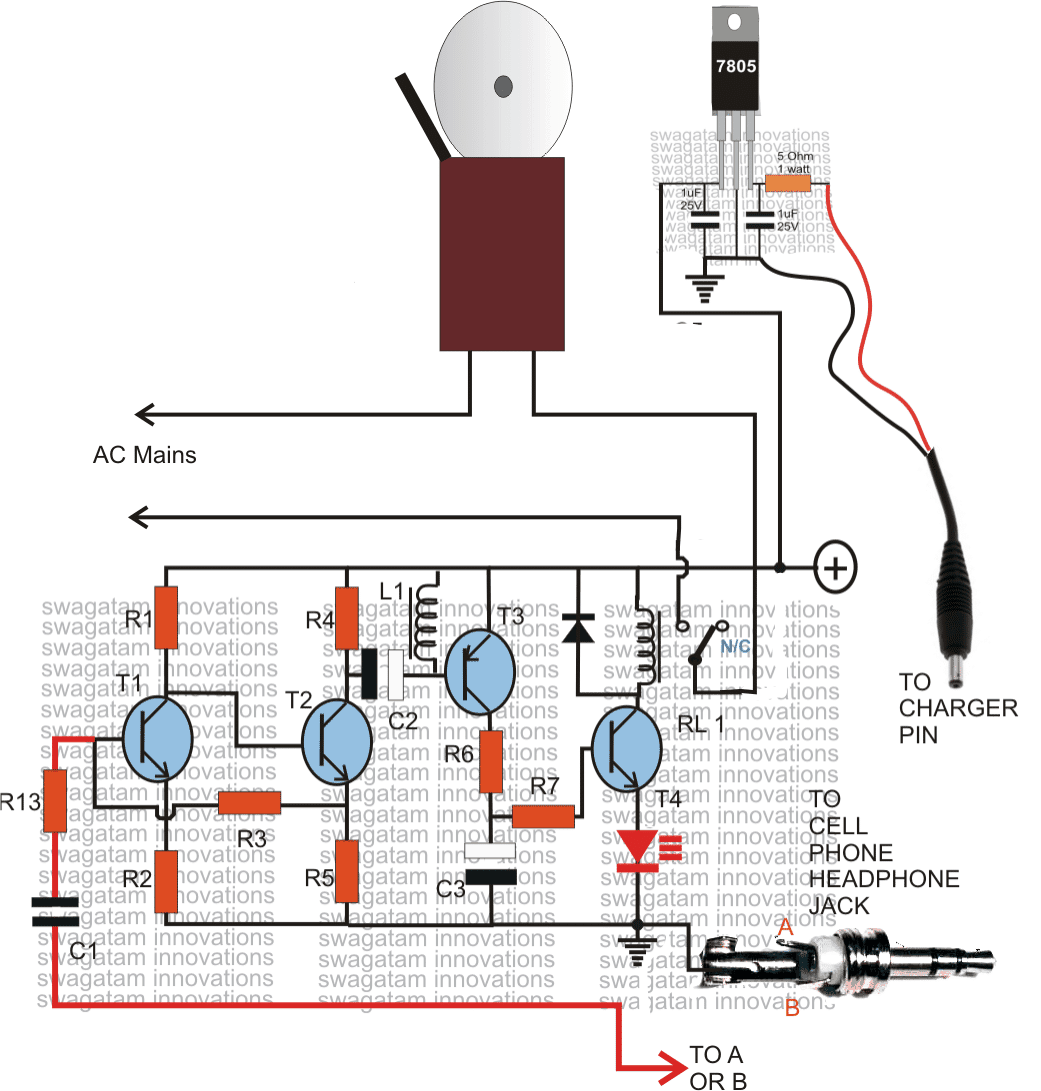
Transistors T1 and T2 form a high gain looped audio amplifier. As can be seen the input signal needs to be derived from a modem cell phone's head phone socket.
A suitably selected ringtone starts playing on the cell phone when called from the users personal cell phone.
The ringtone passes through the headphone connection to the base of T1 via C1, R13.
The preamplifier consisting of T1 and T2 amplifies the signal to reasonable levels and feeds it to the T3 via C2 for further amplification.
T3 boosts the ringtone level to much higher levels, however this signal is still not powerful enough for driving a relay, therefore it is yet further amplified by T4, until finally the drive becomes just suitable for activating the relay.
The relay stays activated only until the incoming cell phone remains connected, on disconnecting the call the relay also disconnects.
The relay contacts may be integrated with a conventional GONG type of bell for the specified actions.
The modem cell phone can be of any type, however it must have the feature of assigning unique ringtones to each specific contact names as per the users preferences.
Here the owners number should be first stored/saved in the modem, then this particular contact name inside the modem should be assigned with a particular continuous type of ringtone.
Next, the default ringtone should be set to "empty".
That's it, the modem cell phone now becomes foolproof and responds to only the owners assigned number.
More than 1 number can be assigned in fact 99 numbers can be assigned which become the unique members of the modem phone book, such that the modem responds only to these numbers, it won't respond to any other unknown or wrong numbers.
Ideally a NOKIA 1280 may be used here as the modem.
Designed BY - "SWAGATAM"
Parts List
- R1 = 22k
- R2 = 220 Ohms,
- R3 = 100K,
- R4,R6,R7 = 4K7
- R5 = 1K
- R13 = 100 ohms,
- T1, T2,T4 = BC547
- T3 = BC557,
- C1 = 0.22uF
- C2,C3 = 100uF/25v
- L1 = 40 mH coil, example: a piezo buzzer coil will do.
- diode = 1N4007
- Relay = 12V/SPDT
- Modem = NOKIA 1280
Charger section parts = as given in the diagram.


Questions & Answers
Hello Swagtam,I really love your work.please can you provide the same system but using SIM Cards(by calling on the SIM Card) to ring the bell please.thanks in advance
Thanks Bryan,
I have posted the circuit here:
https://www.homemade-circuits.com/control-a-relay-on-off-using-sim-card-mobile-phone-and-arduino/
hello sir is it possible to use a cell phone call to start up a generator or motor?
hello yohana, you can try the following circuit:
https://www.homemade-circuits.com/2014/08/cellphone-controlled-car-starter-circuit.html
I am not sure if 30mV would be enough to trigger, but in any case the relay should never activate without an input signal.
the T1/T2 link is correct, there's no problem with this connection, make sure C2 is included in the circuit and the transistor leads are correctly assigned.
try a NOKiA 1280 which is recommended, if you are using any other phone check whether it's headphone jack is generating 100mV or not, check this by selecting mV range on the meter, this much voltage is required minimum for triggering the relay
keep the 3.5 jack out and disconnected from the cell phone modem and check the relay response after powering the circuit….the relay should be off, first confirm this.
Hey Swagatam, This is very interesting project.. I want to build this, But I don't want to use cellphone, I want to use my Land Line phone.. Any idea?
Thanks Farmer, if your landline unit has a headphone jack it can be used for connecting with the input of the above circuit, if it's not there simply open the cabinet, solder two wires with the speaker terminals and join its other ends with the circuits input terminals…that's it, now whenever a call is received the circuit relay will get activated.
Sir,
can i use other this circuit for controlling a bulb..
when we call ,the bulb will light up and when we again call on the mobile the bulb will light off
the above circuit won't toggle the load On/OFF, you will need to make the following design:
https://www.homemade-circuits.com/2012/01/how-to-build-gsm-based-cell-phone.html
good one circuit
hello thanks for the guidance
you are welcome
The circuit is a tested one, it worked well for me.
can i use buzzer instead of electric bell and hence use a dc supply.
you can any type of load AC or DC with the relay contacts, as per your preference.
I have used nokia 5230. I have used 100mh coil as inductor
Sir,
The relay is not working and as a result the circuit is not completed. I also have doubts over the connection of the headphone jack. Please clarify its connections…
which cell phone have you used as the modem? what did you use for L1?
headphone connections are clearly indicated in the diagram
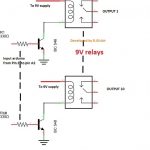
in the video there are 2 relays but in circuit there is only one which one is correct?
the second relay is for activating a connected load ON/OFF as discussed in this post.
https://www.homemade-circuits.com/2012/01/how-to-build-gsm-based-cell-phone.html
resistors are 4.7k
what is the value of R4,R6,R7….???????
Will the mobile set be on continuous charging? Isn't it harmful? I mean overhanging? Thank you
Hello Swagatam,i really appreciate your work it really interesting.On the circuit i see an AC mains from one end and i don't really understand how the AC mains is connected.I will appreciate if you can please explain it to me and what is the AC mains voltage.Also i will like to know if the relay is AC or DC.Thanks
Thanks Louis,
the AC could be the mains 220V input, depending upon the load power specs.
the relay is a DC relay.
can computer speakers or any amplifier can be used to trigger the transistor
yes it's possible.
hi
this can happen in case the pin wiring is short or connected incorrectly or the cellphone ringtone is not delivering sufficient voltage through headphone socket…
connect your headphone pins across base of T1 and ground, check if you are able hear the ringtone or not.
test the circuit without the L1 first, if all's correctly done RL1 will respond instantly to the calls.
16 turns is like a short circuit and that's why your circuit might not be working.
you will have to wind 36swg 1000 turns aprox on a ferrite core to achieve 40mH for L1, which would be enough
If the horn is electromagnetic type then it won't be feasible to amplify it, but if it's an electronic horn then it can be amplified using an external audio amplifier circuit.