The main objective of this car battery warmer circuit is to make sure that even in extremely low temperatures, the battery can be charged and discharged satisfactory.
The design idea was requested by Mr. Elias, as I have explained below.
Design Request and Specifications
My plan is to control a silicone heat pad that runs at 12 VDC and 30 W in order to warm an automobile battery.
Prewarming a lead acid battery is advised in Finland, where temperatures frequently fall below zero degrees Celsius.
In extremely cold temperatures, the battery may not be able to absorb charge current as well as it would in warmer temperatures, like twenty degrees Celsius.
The original idea is to use the battery terminals to provide power directly to the temperature sensor circuit, and an external AC battery charger is used to give power for heating the pad.
But an important question comes up: does a relay provide enough galvanic isolation?
The plan is to use the heater while driving and use the alternator to supply electricity to the heating pad.
Also, I'm thinking of a simple circuit that would only turn on the heater when the voltage reaches a certain, ideally programmable, threshold, like 13.8 volts.
In this setup, the heating pad would only turn on when either of the following two scenarios occurred: either the engine was running and the alternator was working, or the external battery charger was connected and in use.
Circuit Description
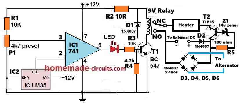
Referring to the above car battery warmer circuit diagram, the working can be understood with the following points:
IC1, which is an IC 741 is configured as a comparator. Therefore, IC1 compares the voltage across its pin#2 and pin#3. As long as its pin#2 potential stays lower than the pin#3 potential, its output remains high and vice versa.
The IC2 LM35 is a temperature sensor IC, used for sensing the temperature of the car battery. Its output voltage (OUT pin) increases by 10mV for each 1° C increase in the temperature around its case.
This output from LM35 IC is attached with the inverting input pin#2 of the IC741.
The non-inverting input pin of IC 741 is attached with a preset P1 which sets or fixes the reference voltage at pin#3 of the IC.
When the atmosphere and the battery temperature are sufficiently warm, the LM35 output at pin#2 of 741 is reasonably higher.
The P1 preset is adjusted such that the pin#3 voltage of IC 741 stays slightly lower than the potential at pin#2 supplied by LM35 output while the atmospheric temperature is not too cold and the battery does not require external warming.
In the above situation, since the pin#3 voltage is slightly lower than pin#2 voltage, the output of IC1 at pin#6 remains at low logic or 0V. This keeps transistor T1 switched OFF causing the relay contacts to be at the N/C position.
At the N/C position the heater stays disconnected and turned OFF. This means as long as the ambient temperature is warm, the heater remains switched OFF.
Now suppose the ambient temperature starts dropping and goes below the predetermined threshold value.
In this situation, the LM35 output also drops until the potential at pin#2 of 741 IC goes below the pin#3 reference voltage value.
This instantly causes the output pin#6 of IC 741 to go high.
When this happens, the relay and the heater are switched ON.
The heater now begins heating the battery until the temperature rises to a point which reverts the situation causing the relay to switch OFF.
The above ON/OFF cycle of the heater continues ensuring that the battery temperature always stays warm and in an optimal condition.
Heater Power Supply
The heater is powered either through the alternator voltage of the car, or through an external AC to DC adaptor.
The transistor T2 along with the zener diode Z1 ensures that the heater is able to turn on only when the supply voltage from the adapter or the alternator is around 14V or higher.
Parts List
- All Resistors are 1/4 watt CFR 5%
- 10k = 2
- 10R, 4.7k, 100R = 1 each
- Preset 4.7k = 1
- Semiconductors
- Transistor BC547, TIP35 = 1 each
- IC LM35 = 1
- IIC 741 = 1
- LED 5mm, 20mA = 1
- Zener diode 14V 1 watt = 1
- Diodes D1, D2, 1N4007 = 2
- Diodes D3, D4, D5, D6 ,1N5402 = 4
- Relay 9V SPDT = 1
- Heater Pad 12V 30 watt = 1


Need Help? Please Leave a Comment! We value your input—Kindly keep it relevant to the above topic!