• Skip to main content
  • Skip to primary sidebar

Homemade Circuit Projects

Need circuit help? Post them in the comments! I've answered over 50,000!

Blog | Categories | About | Contact | Calculators-online
You are here: Home / Sensors and Detectors / Breath Detector Circuit


Breath Detector Circuit

Last Updated on September 1, 2023 by Swagatam 2 Comments

The breath detector circuit I have explained below can be used to check or monitor the breathing function of a human or patient.

Table of Contents
  • Component Functions
  • Circuit Diagram
  • How the Circuit Works

So I have explained the detailed working of the circuit from the following explanation:

Component Functions

LM324 Op amp: A few operational amplifiers (op-amps) in the circuit magnify the minute voltage changes the diode generates. To make sure the signal is powerful enough for additional processing, op-amps are utilized.

LED indicators: One of the LEDs is utilized to show when exhalation is occurring.

The related op-amp amplifies the temperature change brought on by a human exhaling onto the diode, and if it rises beyond a certain threshold, it activates the exhalation LED.

The presence of this LED acts as a visual cue that someone is exhaling onto the sensor.

The other LED serves as an indicator for inhalation.

The accompanying op-amp amplifies the change in temperature of the breath upon inhalation, which causes the inhalation LED to turn on.

This LED lets you know if someone is breathing in or if they've ceased exhaling onto the sensor.

1N4148 Diode: The 1N4148 diode serves as a temperature sensor in this breath detector circuit, which uses it to track variations in breath temperature. It has two LEDs—one to signify exhalation and the other to signify inhalation—and makes use of op-amps for signal amplification.

The exhalation LED turns on when someone exhales onto the sensor, and the inhalation LED turns on when they inhale or cease exhaling, giving a quick visual indicator of breathing patterns.
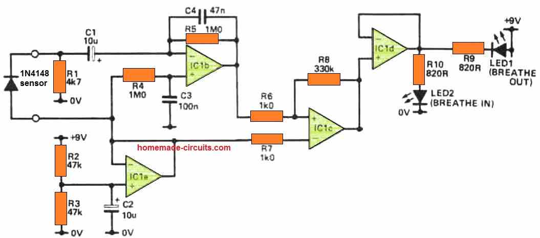
Circuit Diagram

warning message: electricity is dangerous, proceed with caution
breath detector circuit

How the Circuit Works

The analog breath sensor circuit as shown above, is designed to identify your breathing rate and convert it into a suitable digital signal to power the logic circuitry.

The sensing component of the circuit relies on the fact that exhaled air is significantly warmer than when it was inhaled.

While this principle might require further consideration if you intend to measure breathing rates in the midday sun, it performs effectively indoors during chilly winters, even when the central heating is running at full capacity.

The sensing element is quite ordinary, consisting of a 1N4148 diode (or any other suitable type). Surprisingly, it accomplishes its task without any complications.

The input circuit essentially functions as a differentiator, with its rising frequency response moderated by C4.

The output of this circuit drives a comparator, which, in turn, controls the logic circuitry (enhanced by the Schmitt trigger for sharp signal edges).

The inclusion of an LED circuit is optional; it illuminates one of the diodes based on whether you are inhaling or exhaling, serving as a useful test tool to confirm the proper positioning of the sensing diode and the functionality of the input circuit.

However, it does introduce an additional current draw to the circuit, so the choice of its inclusion is left to your discretion.

The remaining operational amplifier's primary role is to establish a reference point at half the battery voltage for the other integrated circuits.

You'll also like:

  • 1.  Make this Temperature Indicator Circuit with Sequential LED Display
  • 2.  Simple Audio Spectrum Analyzer Circuit
  • 3.  Precision Current Sensing and Monitoring Circuit using IC NCS21xR
  • 4.  Make this Touch free Faucet Circuit for Hands-free Tap Control
  • 5.  Knock Activated Door Security Intercom Circuit
  • 6.  How to Make LED/LDR Opto Coupler

Filed Under: Sensors and Detectors Tagged With: Breath, Detector

About Swagatam

I am an electronics engineer and doing practical hands-on work from more than 15 years now. Building real circuits, testing them and also making PCB layouts by myself. I really love doing all these things like inventing something new, designing electronics and also helping other people like hobby guys who want to make their own cool circuits at home.

And that is the main reason why I started this website homemade-circuits.com, to share different types of circuit ideas..

If you are having any kind of doubt or question related to circuits then just write down your question in the comment box below, I am like always checking, so I guarantee I will reply you for sure!

Previous Post: « Ding Dong Bell Circuit that Saves Electricity
Next Post: How to Measure Very Low Current [Circuit Diagram] »

Reader Interactions

Comments

  1. Sree says

    March 29, 2024 at 6:08 pm

    what are the specifications of resistors uesd?

    Reply
    • Swagatam says

      March 29, 2024 at 6:43 pm

      All are 1/4 watt 5% CFR..

      Reply

Need Help? Please Leave a Comment! We value your input—Kindly keep it relevant to the above topic! Cancel reply

Your email address will not be published. Required fields are marked *

Primary Sidebar

circuit simulator image

Subscribe to New Posts


Categories

  • Arduino Projects (89)
  • Audio and Amplifier Projects (132)
  • Automation Projects (17)
  • Automobile Electronics (101)
  • Battery Charger Circuits (83)
  • Datasheets and Components (104)
  • Electronics Theory (143)
  • Free Energy (37)
  • Games and Sports Projects (11)
  • Grid and 3-Phase (19)
  • Health related Projects (25)
  • Home Electrical Circuits (12)
  • Indicator Circuits (14)
  • Inverter Circuits (88)
  • Lamps and Lights (142)
  • Meters and Testers (69)
  • Mini Projects (46)
  • Motor Controller (64)
  • Oscillator Circuits (27)
  • Pets and Pests (15)
  • Power Supply Circuits (108)
  • Remote Control Circuits (50)
  • Security and Alarm (64)
  • Sensors and Detectors (101)
  • Solar Controller Circuits (59)
  • Temperature Controllers (42)
  • Timer and Delay Relay (49)
  • Transmitter Circuits (29)
  • Voltage Control and Protection (39)
  • Water Controller (36)


Other Links

  • Privacy Policy
  • Cookie Policy
  • Disclaimer
  • Copyright
  • Videos
  • Sitemap


People also Search

555 Circuits | 741 Circuits | LM324 Circuits | LM338 Circuits | 4017 Circuits | Ultrasonic Projects | SMPS Projects | Christmas Projects | MOSFETs | Radio Circuits | Laser Circuits | PIR Projects |

Social Profiles

  • Twitter
  • YouTube
  • Instagram
  • Pinterest
  • My Facebook-Page
  • Quora
  • Stack Exchange
  • Linkedin


  • Recent Comments

    • Swagatam on How Shunt Regulator TL431 Works, Datasheet, Application
    • SA on How Shunt Regulator TL431 Works, Datasheet, Application
    • Farmtech on Free Energy Generator Circuit – The N-Machine
    • Nitesh Agrawal on How to Design Simple LED Driver Circuits
    • Swagatam on How to Design Simple LED Driver Circuits

    © 2025 · Swagatam Innovations