In this post I have explained a circuit which controls a submersible borewell motor by operating its red (Start) and green (Stop) buttons, in response to low level, high level water conditions, and also in a condition where the motor may experience a dry run situation. The idea was requested by Mr. Vamsi.
Automatic Start/Stop Controller for Borewell Contactor
Hi sir, i'm an electronics hobbyist and a regular viewer of ur blog , also a very big fan for U sir... 🙂 i have learned very much from YOU. and THANK YOU VERY MUCH SIR... 🙂
Sir, can u pls suggest me, i need the circuit design of fully automatic water overflow controller cum dry run protector circuit with showing level indicators.
The circuit needed for the borewell starter like generally all of the borewell starters will have a GREEN and a RED push type buttons. manually we will start up the motor by pressing the GREEN for 1sec. and 1sec. for shutting OFF as the same way, the design i need is, the controller works with Dual Relay ( 2 individual Relays) one is for starting winding.
i.e Relay1 activates for 1 sec. to START motor and the other Relay2 is to STOP the motor activates for 1 sec. respectively and the main thing is we can not drop sensors such a lengthy to the ground level of the deep wells
so, all i need is in case if there is less water in the bore well, the sensor in the OHT is connected to upper water pipe which falls in the tank,sensors should activate and energise the Relay2 which in turn shutting OFF the motor if water discharges very low. the water which discharges from the pipe will take atleast 15sec. so, it will be needed ON time delay for at least 20 sec.(relay1 activates and wait for water discharge up to mentioned time.)
Now the motor should works in these conditions:
1.when water low level in OHT, Relay1 gets energized for 1sec & switching ON the motor.
2 Relay2 should activates in two conditions: a) when water filled up in OHT activates for 1sec. shutting OFF motor , and b) when borewell DRY RUN, time delayed for at least for 20sec and activates the Relay2 for 1sec to shut OFF the motor.
The circuit need to works in 12v dc. and also if possible need a RESET push button, when the water in the OHT is suppose a half of the tank, if we need to make tank full, the motor should start by pressing RESET button.
This is my brief explanation. i tried very much for this desired circuit design. but i'm not such expert to say but i have a technical, logical and basic knowledge in this field. i hope that u understand my request. Pls do the needful Sir, Hopefully awaiting for ur valuable reply. For posting the circuit diagram, my ID : login2vamsi183@gmail.com
Thanks and Regards
Vamsi Krishna
The Design
In a couple of my earlier articles, I discussed about a similar circuit concerning a semi-automatic submersible pump controller circuit, however the design utilized an ordinary moisture sensing metal probes for the detection and activation.
The present design relies on a reed/magnet based float switch operation, which not only makes the operations easier but also a lot reliable.
The proposed submersible borewell motor starter controller circuit may be understood by referring to the following diagram:
Circuit Diagram
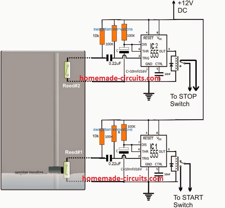
The diagram above shows a very straightforward set up using a couple of identical IC 555 monostable stages.
The IC2 stage forms the submersible pump starter circuit, while the IC2 stage is positioned to stop the pump switch.
Both the circuits work with reed switches (float switch) which may be seen positioned inside the overhead tank, one at the bottom, the other at the top of the tank.
The bottom reed closes when the water level is near the bottom threshold, and parallel to the reed switch, while the upper reed switch closes when the water level reaches at the level where its been installed.
Assuming the water level to be near the bottom reed switch, the reed switch closes, triggering the IC1 stage, which in turn momentarily clicks the associated relay.
The relay being wired across the START button of the submersible pump, the motor gets initiated and it starts pumping water to the overhead tank.
The water level in the OHT now begins rising, and when it reaches near the upper reed switch reed#2, it closes triggering the IC2 relay for a moment activating the STOP switch of the motor. The motor now stops and discontinues the pumping of water inside the OHT.
Motor Dry Run Protection
As requested, the STOP circuit also needs to be signaled in case a dry running of the motor is detected.
In the absence of water to pump, the motor may be subjected to a "dry run" situation which in turn might heat up the motor to dangerous levels.
A simple heat sensor thus can be introduced to sense the rising heat of the pump motor and signal the IC1 stage so that the STOP button is instantly activated on time and the motor is saved from burning.
A simple yet very effective heat sensor circuit may be witnessed below. It ensures the vital dry run protection for the borewell motor and also facilitates the action externally without
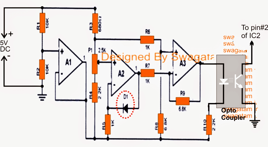
Using 3 opamps from IC LM324
The circuit is configured around three opamps (LM324 or three separate 741 ICs), where A2 forms the temperature sensor through D1.
D1 which is a 1N4148 diode is used as an effective heat sensor, and is supposed to be glued to the motor body for the sensing.
P1 is set such that when the motor tends to heat up, the output of A3 becomes high enough to trigger the opto transistor into conduction, therefore in case a motor goes through a dry run situation and begins getting hotter, D1 detects this triggering the connected opto coupler (4n35).
Now since the collector of the opto coupler is attached with the pin#2 of IC2 (STOP relay), the IC2 responds to this and quickly initiates the relay and halts the motor.
The motor gradually cools down, which causes the opto coupler too to shut down and the situation reverts to normal and in the original state.
The IC 555 based START/STOP circuit explained above was successfully built by one of the avid readers of this blog Mr. Chandan. The tested values of the R and C components as shown in the figures are for producing a 2 sec ON delay for the relevant start/stop switches. The values were suggested by Mr. Chandan.


Comments
Dear sir,
i REALLY VERY APPRECIATE and THANK YOU VERY MUCH for the HELP and the earlier response. Sir, i like to ask about here in this circuit instead of using float switch, is there any other option through modifying the circuit to use with steel probes or cable lugs as sensors..? and for the dry run protection can't we make this circuit as similar to the circuit which u have posted in ( https://www.homemade-circuits.com/2013/07/underground-water-pump-motor-dry-run.html ) coz, we can not fix the heat sensor as such deeper our bore well depth is more than 600 feet and i think it is expensive and too difficult to do. so, can u design the circuit accordingly the above requirement along with showing 4 level indicators to this circuit. if it's possible kindly i request u pls modify the needful.
THANKS & REG.
VAMSI KRISHNA
Hello sir, can i use a ups transformer to design an inverter
yes you can use it…