• Skip to main content
  • Skip to primary sidebar

Homemade Circuit Projects

Need circuit help? Post them in the comments! I've answered over 50,000!

Blog | Categories | About | Contact | Calculators-online
You are here: Home / Arduino Projects / Arduino PWM Signal Generator Circuit

Arduino PWM Signal Generator Circuit

Last Updated on December 5, 2024 by Swagatam Leave a Comment

In this post we elaborately study how to make an Arduino based PWM signal generator circuit, which can be set or adjusted with a potentiometer or a pot to any preferred duty cycle ratio.

By Ankit Negi 

WHAT IS PWM?

pwm or pulse width modulation as the name itself suggest is  modulation of width of the pulses  i.e. how long the pulse is high or low in a given time period. This changes duty cycle of the pulse which eventually determines the average value of pulse as duty cycle is on time divided by total time period.

And frequency plays very important role in pwm, which must be high enough to generate stable output

Pwm is done for variety of purposes like driving a device that works on low voltage or for switching purposes like in SMPS.

PWM USING ARDUINO UNO

Pwm is also one of the factors that make arduino a simplest development board, as pwm can be done by adding just one line code to your program. Note that there are separate digital pins available on arduino UNO for pwm which means these pins can give pwm output.

There are total 6 pwm pins available on arduino UNO that are 3, 5, 6,9,10 and11 out of 14 digital pins. Note that number of pwm pins vary from one type of arduino board to another.

Now there are two ways in which pwm can be performed by arduino:

1. By directly assigning an analog value to the pwm pin between 0 and 255.

Since digital pins in arduino can provide maximum of 5v that means 0 analog value is equal to 0 volts and 255 is equivalent to 5 volts.

And to perform this you have to just add this code to your program:

analogWrite( PWM pin no, value between 0 to 255);

For example:   analogWrite(10,64);// write 64 analog value to pwm pin no 10.

Now this means:: (5/255)*64 volts=  1.25volts i.e. 25% duty cycle.

2. By assigning value according to the input received from analog pins of arduino.
Input can be taken from components like an IR sensor or a potentiometer.

Note that arduino receive analog input in terms of  value between 0 to 1023 which is equivalent to 0 to 5 volts.  So to perform pwm on a pin you must convert this input value in equivalence to number between 0 to 255 and this is called mapping in arduino’s language.

There is a simple code for this:

y= map(x,0,1023:0,255);// where x is the input variable

After this you can perform pwm on a pin using:

analogWrite(PWM pin no,y);// write received mapped value to pin 10

PWM EXAMPLE:

We are going to learn both the technique with this example. For this you need:

1. A potentiometer
2. Two  leds
3. Two 100 ohm resistors

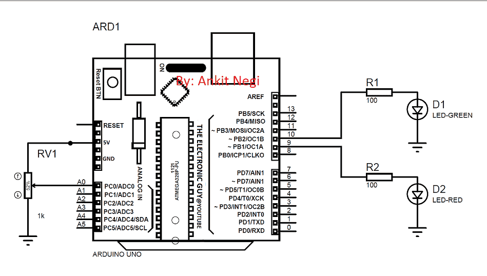
Make connections as shown in circuit diagram:

CIRCUIT DIAGRAM:

circuit 2

CODE:

int x;// initialise variables
int y;
void setup() {
pinMode(10,OUTPUT);//initialise pin 10 as output
pinMode(9,OUTPUT);//initialise pin 9 as output
pinMode(A0,INPUT);//initialise pin A0 as input from pot.
// put your setup code here, to run once:
}
void loop() {
analogWrite(9,125);// directly assigning value to pin 9 i.e. case1
x=analogRead(A0);// read values from potentiometer in terms of voltage
y= map(x,0,1023,0,255);// map those values from 0 to 255 // put your main code here, to run repeatedly:
analogWrite(10,y);// assigning value based on input from pot at pin A0 i.e. case 2
}

How it Works

The basic working of the proposed Arduino PWM signal generator project can be studied from the following paragraph

Pin no 9 can be assigned arbitrary pwm value whereas pin no. 10 gives pwm value in accordance to the position of the potentiometer with respect to ground. Keep changing this arbitrary value for pin 9 as well as rotate potentiometer to see different pwm output on both pins.

You'll also like:

  • 1.  Raspberry Pi Explained
  • 2.  Arduino Pure Sine Wave Inverter Circuit with Full Program Code
  • 3.  Arduino Musical Tune Generator Circuit
  • 4.  SMS Based Water Supply Alert System
  • 5.  How to Drive High Watt LEDs with Arduino
  • 6.  Color Detector Circuit with Arduino Code

About Swagatam

I am an electronics engineer with over 15 years of hands-on experience. I am passionate about inventing, designing electronic circuits and PCBs, and helping hobbyists bring their projects to life. That is why I founded homemade-circuits.com, a website where I share innovative circuit ideas and tutorials. Have a circuit related question? Leave a comment.... I guarantee a reply!

Previous Post: « High Current Motor Control Circuit using Arduino
Next Post: 2.4 GHz 10 Channel Remote Control Switch Circuit »

Reader Interactions

Need Help? Please Leave a Comment! We value your input—Kindly keep it relevant to the above topic! Cancel reply

Your email address will not be published. Required fields are marked *

Primary Sidebar

Subscribe to New Circuit Ideas

Categories

  • Arduino Projects (87)
  • Audio and Amplifier Projects (132)
  • Automation Projects (17)
  • Automobile Electronics (101)
  • Battery Charger Circuits (82)
  • Datasheets and Components (102)
  • Electronics Theory (143)
  • Free Energy (37)
  • Games and Sports Projects (11)
  • Grid and 3-Phase (19)
  • Health related Projects (25)
  • Home Electrical Circuits (12)
  • Indicator Circuits (14)
  • Inverter Circuits (87)
  • Lamps and Lights (142)
  • Meters and Testers (69)
  • Mini Projects (46)
  • Motor Controller (64)
  • Oscillator Circuits (27)
  • Pets and Pests (15)
  • Power Supply Circuits (108)
  • Remote Control Circuits (50)
  • Security and Alarm (64)
  • Sensors and Detectors (100)
  • Solar Controller Circuits (59)
  • Temperature Controllers (42)
  • Timer and Delay Relay (49)
  • Transmitter Circuits (29)
  • Voltage Control and Protection (37)
  • Water Controller (36)

Calculators

  • Battery Back up Time Calculator
  • Capacitance Reactance Calculator
  • IC 555 Astable Calculator
  • IC 555 Monostable Calculator
  • Inductance Calculator
  • LC Resonance Calculator
  • LM317, LM338, LM396 Calculator
  • Ohm’s Law Calculator
  • Phase Angle Phase Shift Calculator
  • Power Factor (PF) Calculator
  • Reactance Calculator
  • Transistor Astable Calculator
  • Transistor base Resistor Calculator
  • Voltage Divider Calculator
  • Wire Current Calculator
  • Zener Diode Calculator
  • Filter Capacitor Calculator
  • Buck Converter Calculator
  • Boost Converter Calculator
  • Solar Panel, Inverter, Battery Calculator
  • Wire Current Calculator
  • SMPS Transformer Calculator
  • IC SG3525, SG3524 Calculator
  • Inverter LC Filter Calculator

People Also Search

555 Circuits | 741 Circuits | LM324 Circuits | LM338 Circuits | 4017 Circuits | Ultrasonic Projects | SMPS Projects | Christmas Projects | MOSFETs | Radio Circuits | Laser Circuits | PIR Projects |

Recent Comments

  • Swagatam on Simple Delay Timer Circuits Explained
  • Swagatam on The Role of Inductor Coil in SMPS
  • Swagatam on 7 Modified Sine Wave Inverter Circuits Explored – 100W to 3kVA
  • Swagatam on 7 Modified Sine Wave Inverter Circuits Explored – 100W to 3kVA
  • Victor on 7 Modified Sine Wave Inverter Circuits Explored – 100W to 3kVA

Company

  • Privacy Policy
  • Cookie Policy
  • About Me
  • Contact
  • Disclaimer
  • Copyright
  • Videos
  • Sitemap

Social Profiles

  • Twitter
  • YouTube
  • Instagram
  • Pinterest
  • My Facebook-Page
  • Quora
  • Stack Exchange
  • Linkedin
  • © 2025 · Swagatam Innovations