The thermistor name has been devised as a short form for the “thermally sensitive resistor”. The full form of the thermistor provides the general and the detailed idea of the action which is the feature of the thermistor.
By: S. Prakash
The various different types of the devices in which the thermistor are used include a wide range of devices such as temperature sensors and electronic circuits where they provide temperature compensation.
Although the usage of the thermistor is not as common as the transistors, resistors, and capacitors of the ordinary form, the electronic field uses the thermistors at a large scale.
Symbol of the Thermistor Circuit
The symbol which is used by the thermistor for its recognition is the circuit symbol of its own.
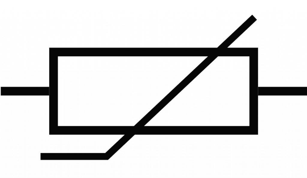
The circuit symbol of a thermistor consists of a base which is made up of standard resistor rectangle along with a diagonal line which passes through the base and consists of a vertical section of a small size.
The circuit diagrams widely use the circuit symbol of the thermistor.
Types of Thermistor
The thermistor can be divided into various types and categories based on a number of different ways.
These ways in which they are to be categorized are firstly based on the manner in which the thermistor reacts to the exposure of heat.
The resistance of some of the capacitors increases with the increase in the temperature while the opposite is observed in the other types of thermistor resulting in the decrease in the resistance.
This idea can be expanded by the thermistor’s curve which can be depicted by an equation of simple form:
Relationship Between Resistance and Temperature
ΔR = k x & ΔT
The above equation constitutes of:
ΔR = Resistance’s change observed
ΔT = Temperature’s change observed
k = temperature coefficient of resistance of first order
There is a non-linear relationship between the resistance and temperature in majority of the cases. But with the various small changes in the resistance and temperature, there is a change in the relationship as well which is observed and the relationship becomes linear in nature.
The value of the “k” can be either positive or negative depending on the type of the thermistor.
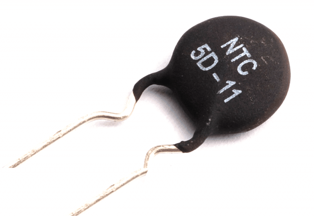
NTC Thermistor (Negative Temperature Coefficient Thermistor): The property of the NTC Thermistor enables it to decrease its resistance with the increase in the temperature and thereby the “k” factor for the NTC thermistor is negative.
PTC Thermistor (Positive Temperature Coefficient Thermistor): The property of the NTC Thermistor enables it to increase its resistance with the increase in the temperature and thereby the “k” factor for the NTC thermistor is positive.
Another way in which the thermistor can be differentiated and categorized apart from their resistance change feature is dependent on the material type which is used for the thermistor. The material being used is of two major types:
Single crystal semiconductors
Compounds which are metallic in nature such as oxides
Thermistor: Development and History
The phenomenon of the variation observed in the resistor due to changes in the temperature was demonstrated in the early nineteenth century.
There are many ways in which the thermistor has continued to be used till date. But a majority of this thermistor suffers from the drawback that they are able to show very small variation in resistance in correspondence to the large range of temperature.
The usage of the semiconductors is generally implied in the thermistors which enable the thermistors to show larger variations in resistance in correspondence to the large range of temperature.
The materials which are used for the manufacturing of thermistor are of two types including the metallic compounds which were the first materials to be discovered for thermistor.
In 1833, while measuring the variation in the resistance with respect to the silver sulphide’s temperature, Faraday discovered the negative temperature coefficient. But the availability of the metallic oxides at a large scale commercially occurred only in the 1940s.
The investigation of the silicon thermistor and the crystal germanium thermistor were carried out post the Second World War while the study of the semiconductor materials was being done.
Although the semiconductor and the metallic oxides are two thermistor types, the temperature ranges covered by them are different and thus they need not compete.
Composition and Structure of Thermistor
On the basis of the applications in which the thermistor needs to be used along with the range of the temperature range over which the thermistor is going to operate; the sizes, shapes, and the material type used to manufacture the thermistor is decided.
In case the applications in which the flat surface needs to be in constant contact by the thermistor; the shape of the thermistor in these cases is of flat discs.
In case, there are temperature probes for which the thermistor needs to be made then the shape of the thermistor is in the form of rods or beads. Thus, the requirements which are adherent to the applications for which the thermistor will be used directs the thermistor’s actual physical shape.
The range of temperature for which the thermistor of the metallic oxide type is used is 200-700 K.
The component which is used to manufacture these thermistors is found in the version of a fine powder which is sintered and compressed at a very high temperature.
The materials which are most commonly used for these thermistors include nickel oxide, ferric oxide, manganese oxide, copper oxide, and cobalt oxide.
The temperatures for which the semiconductor thermistors are used are very low. The silicon thermistors are used less frequently than the germanium thermistors which are used more widely for the temperatures which are in the range that is below the range of 100º of absolute zero i.e. 100K.
The temperature for which the use of the silicon thermistor can be done is to the maximum of 250K. If the temperature increases more than 250K, then the silicon thermistor experiences the setting in of the positive temperature coefficients. A single crystal is used to manufacture the thermistor wherein the level at which the doping of the crystal is carried out is 10^16 - 10^17/cm3.
Applications of Thermistor
The thermistor can be used for many different types of applications and there are many other applications in which they are found.
The most attractive feature of the thermistor which makes them popular to be used in the circuits is that the elements provided by them in the circuits are very cost effective since they perform effectively and yet are available at cheap price.
The fact that whether the temperature coefficient is negative or positive determines the applications in which the thermistor can be used.
In case the temperature coefficient is negative, the thermistor can be used for the following applications:
Thermometers of very low temperature: the thermistors are used to measure the temperature of very low levels in the thermometers of very low temperature.
Digital thermostats: The digital thermostats of the modern day use the thermistors widely and commonly.
Battery Pack Monitors: The battery packs’ temperature throughout the period they are charged is monitored through the use of the NTC thermistors.
Some of the batteries which are used in the modern day industry are sensitive towards overcharging including the widely used Li-ion batteries. In such batteries their charging state is effectively indicated by the temperature and thereby enabling the determination of the time when the charging cycle needs to be terminated.
In-rush protection devices: The power supply circuits use the NTC thermistors in the form of devices which limits the in-rush current.
The NTC thermistors while acting as the in-rush protection devices prevents the flow of large amounts of current at the point of turn-on and by providing an initial level of high resistance.
After this, the thermistor gets heated and thus the initial level of resistance being provided by it decreases substantially thereby allowing the flow of high amounts of current during the circuit’s normal operation.
The thermistors used for the purpose of this application are designed accordingly and thus their size is larger in comparison to the measuring type thermistors.
In case the temperature coefficient is positive, the thermistor can be used for the following applications:
Current limiting devices: The electronic circuits use the PTC thermistors in the form of current limiting devices.
The PTC thermistors act as an alternative device for the more commonly used fuse. There are no undue or side effects caused by the heat which is generated in small amounts when the device experiences a flow of current during normal conditions.
But in case the flow of the current through the device is very large then it may result in the increase in the resistance since the heat may not be dissipated in the surroundings since the device may be unable to do so.
This results in the generation of more heat thereby producing a phenomenon of positive feedback effect. The device is protected by such heat and fluctuation in current since the fall in current is observed when there is increase in the resistance.
The applications in which the thermistors can be used are of a wide range. Thermistors can be used to sense temperatures in a reliable, cheap (cost-effective), and simple manner.
The various devices in which the thermistors can be used include thermostats and fire alarms. Thermistors can be used alone as well along with in the unison of other devices. In the latter case, thermistor can be used to provide accuracy of high degrees by making it a part of the Wheatstone Bridge.
Also, the thermistors are used in the form of temperature compensation devices.
In a large percentage of the resistors, there is an increase in the resistance which is observed with a corresponding increase in the temperature due to their positive temperature coefficient.
In case, there is a high requirement of stability by the applications, the thermistor which possesses negative temperature coefficient is used. This is achieved when the circuit incorporates the thermistor in order to counteract the component’s effects produced due to their positive temperature coefficient.


Questions & Answers
The value of the “k” can be either positive or negative depending on the type of the thermistor. After that there is NTC for both NTC and PTC types .
How can i convert 220v AC to 27-36v DC for LED bulb
You can use a transformer or refer to the following article for other options:
https://www.homemade-circuits.com/how-to-make-led-bulb-circuit/
Greetings to you sir,am happy to have discovered your site.I appreciate every circuit, thanks for your good works.
Glad you liked my website…thanks for the feedback!
Hello, Can you please explain how exactly are you using this meter? because If you use it within its limits, it will never burn, meaning if the measurement is done within 1000V range, the meter won't burn?
Gabriel, you can refer to the following article for the details:
https://www.homemade-circuits.com/2015/01/calculating-capacitor-current-in.html
Thanks Gabriel,
acquiring 10 amp from a 4.5 amp source is impossible, from where do you expect to get the extra 5.5 amps from? sorry that's not feasible.